background image

Notice


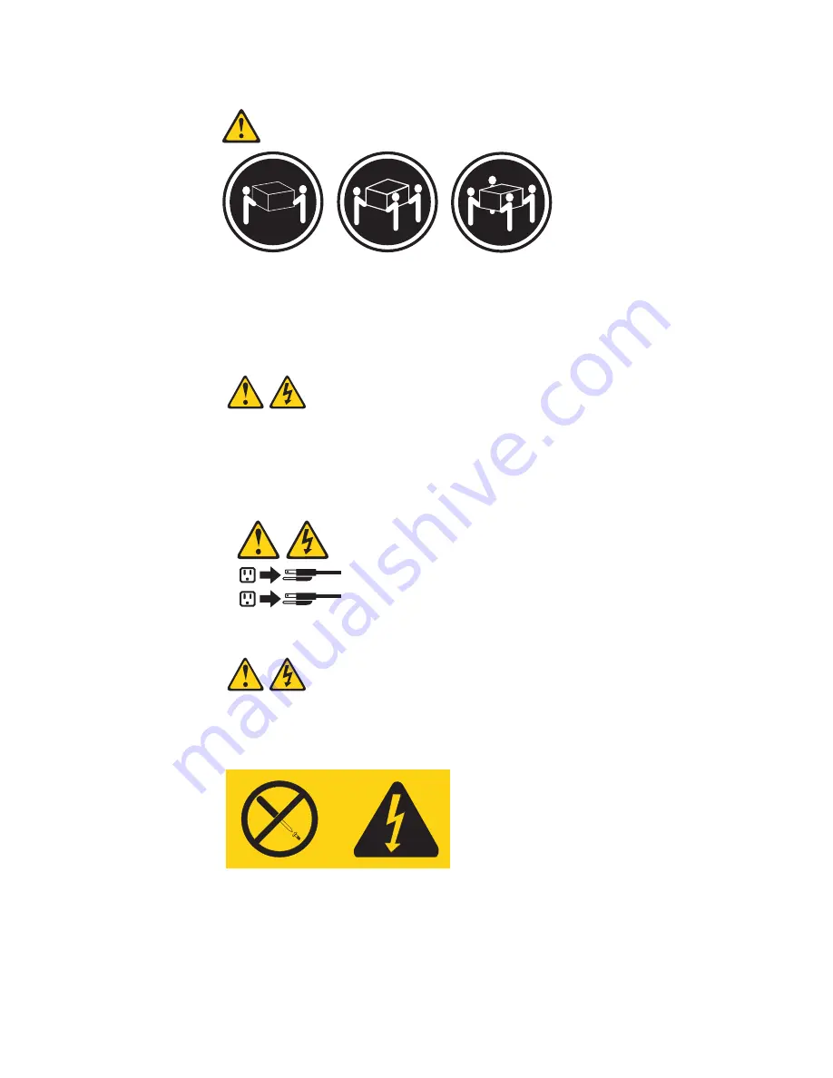
4


18


kg


(39.7


lb)


32


kg


(70.5


lb)


55


kg


(121.2


lb)


ATTENTION:


Faites-vous


aider


pour


soulever


ce


produit.


Notice


5


ATTENTION:


Le


bouton


de


mise


sous


tension/hors


tension


de


l’unité


et


l’interrupteur


d’alimentation


du


bloc


d’alimentation


ne


coupent


pas


l’arrivée


de


courant


électrique


à


l’intérieur


de


la


machine.


Il


se


peut


que


votre


unité


dispose


de


plusieurs


cordons


d’alimentation.


Pour


isoler


totalement


l’unité


du


réseau


électrique,


débranchez


tous


les


cordons


d’alimentation


des


socles


de


prise


de


courant.


1

2


Notice


8


ATTENTION:


N’ouvrez


jamais


le


bloc


d’alimentation


ou


tout


élément


sur


lequel


e


apposée


l’étiquette


ci-dessous.


Des


tensions


et


des


courants


dangereux


sont


présents


à


l’intérie


de


tout


composant


sur


lequel


est


apposée


cette


étiquette.


Ces


éléments


ne


peuvent


pas


être


réparés.


Si


vous


pensez


qu’ils


peuvent


être


à


l’origine


d’un


incident,


prene


contact


avec


un


technicien


de


maintenance.


122


Eserver


325


Type


8835:


Hardware


Maintenance


Manual


and


Troubleshooting


Guide

Содержание 8835 - Eserver 325 - 1 GB RAM

Страница 1: ...Eserver 325 Type 8835 Hardware Maintenance Manual and Troubleshooting Guide ERserver...

Страница 2: ......

Страница 3: ...Eserver 325 Type 8835 Hardware Maintenance Manual and Troubleshooting Guide ERserver...

Страница 4: ...ent version of this document is available at http www ibm com pc support Fifth Edition November 2004 Copyright International Business Machines Corporation 2002 2003 All rights reserved US Government U...

Страница 5: ...Accertarsi di leggere tutti gli avvisi di attenzione e di pericolo prima di effettuare qualsiasi operazione Lea atentamente todas las declaraciones de precauci n y peligro ante de llevar a cabo cualqu...

Страница 6: ...iv Eserver 325 Type 8835 Hardware Maintenance Manual and Troubleshooting Guide...

Страница 7: ...ure 14 Diagnostic tools overview 15 Power on self test 15 POST beep codes 15 POST error messages 16 Diagnostic programs and error messages 16 Text messages 17 Downloading the diagnostics program 17 St...

Страница 8: ...em board 64 System board internal connectors 64 System board external connectors 65 System board LEDs 66 System board option connectors 67 System board connectors for adapters DIMMs and other componen...

Страница 9: ...Trademarks 144 Important notes 144 Product recycling and disposal 145 Battery return program 145 Electronic emission notices 146 Federal Communications Commission FCC statement 146 Industry Canada Cla...

Страница 10: ...viii Eserver 325 Type 8835 Hardware Maintenance Manual and Troubleshooting Guide...

Страница 11: ...le expansion capabilities for the future The model number and serial number are on the ID label on the right mounting bracket on the server as shown in the following illustration Note This illustratio...

Страница 12: ...ou can use to locate the corresponding statement in your language in the Safety Information book Depending on your server model additional publications might be included on the IBM Eserver Documentati...

Страница 13: ...controller v One single channel LSI Ultra320 SCSI controller v Two Broadcom 10 100 1000 Ethernet controllers dual port design with Wake on LAN v Four Universal Serial Bus USB ports v One serial port v...

Страница 14: ...is flashing it indicates that the server is in turned off and still connected to an ac power source When this LED is off it indicates that ac power is not present or the power supply or the LED itsel...

Страница 15: ...d during startup For detailed information about this option and how to connect it to your server see the documentation that comes with the option For information about the Configuration Setup Utility...

Страница 16: ...rom the server you must disconnect the power cord from the electrical outlet Gigabit Ethernet 1 LAN 1 connector Use this connector to connect the server to a network Gigabit Ethernet 2 LAN 2 connector...

Страница 17: ...rical current supplied to the device The device also might have more than one power cord To remove all electrical current from the device ensure that all power cords are disconnected from the power so...

Страница 18: ...cessor can turn off the server as an automatic response to a critical system failure v You can turn off the server through a request from the service processor 8 Eserver 325 Type 8835 Hardware Mainten...

Страница 19: ...ices that are attached to it ServeRAID Manager ServeRAID Manager is available as a stand alone program and as an IBM Director extension If a ServeRAID adapter is installed in your server or if you are...

Страница 20: ...iew or change SCSI IDs for attached devices Set SCSI protocol parameters on SCSI hard disk drives v Use ServeRAID Manager to Configure arrays View your RAID configuration and associated devices Monito...

Страница 21: ...the User s Guide on the IBM Eserver Documentation CD Complete the following steps to update the firmware v Using Linux or Windows run the Linux or Windows update package obtained from the web if avai...

Страница 22: ...12 Eserver 325 Type 8835 Hardware Maintenance Manual and Troubleshooting Guide...

Страница 23: ...es might not occur the next time you run the test A failed server might be part of a shared hard disk drive cluster two or more servers sharing the same external storage devices Before running the dia...

Страница 24: ...t all display controls to the middle position 4 Turn on all external devices 5 Turn on the server 6 Record any POST error messages that are displayed on the screen If an error is displayed look up the...

Страница 25: ...check the operation of system components and some of the installed options If POST finishes without detecting any problems the first window of the operating system opens or an application program appe...

Страница 26: ...should be performed by trained service personnel Sometimes the first error to occur causes additional errors In this case the server displays more than one error message Always follow the suggested a...

Страница 27: ...diagnostic test such as when a device that is to be tested is not installed test specific string is additional information that is used to analyze the problem Downloading the diagnostics program Compl...

Страница 28: ...st Startup Device 8 Press Esc two times to return to the Configuration Setup Utility menu 9 Place the IBM Enhanced Diagnostics CD in the CD ROM drive 10 Select Save Exit Setup and follow the prompts T...

Страница 29: ...6 Notes 1 Depending on the configuration some of the error messages might not appear when you run the diagnostic programs 2 If diagnostic error messages appear that are not listed in the tables make s...

Страница 30: ...and viewing the test log on page 18 to find out the cause of the error Error Power LED J20 SCSI LED header J19 Fan 1 error LED DLED2 Fan 2 error LED DLED4 Microprocessor 2 error LED DLED14 Fan 3 erro...

Страница 31: ...u can update the BIOS code for the server through one of the following methods v Downloading the latest BIOS code from the IBM Web site creating an update diskette and using an external USB diskette d...

Страница 32: ...everal minutes of apparent inactivity during this process 11 After the recovery completes turn off the server monitor and peripheral devices 12 Disconnect all power cords and external cables then remo...

Страница 33: ...overing from a POST BIOS update failure on page 21 Attention Do not change settings or move jumpers on any system board switch or jumper blocks that are not shown in this book Complete the following s...

Страница 34: ...Turn off the server and disconnect all ac power cords 2 Check for loose cables in the power subsystem Also check for short circuits for example if there is a loose screw causing a short circuit on a c...

Страница 35: ...the cabling instructions that come with optional adapters v You have replaced a failed fan as soon as possible Handling static sensitive devices Attention Static electricity can damage electronic devi...

Страница 36: ...ight differ slightly from your hardware Note The illustrations in this publication might differ slightly from your hardware Microprocessor heat sink Microprocessor Dual inline memory module DIMM Syste...

Страница 37: ...erver Attention To ensure adequate cooling and airflow do not operate the server with the cover removed Operating the server with the cover removed will damage server components 5 If you are installin...

Страница 38: ...supports 3 3 V and universal PCI and PCI X adapters it does not support 5 0 V only adapters v The integrated video controller is on PCI bus 1 The integrated Ethernet controllers and the integrated SC...

Страница 39: ...lowing illustration shows the cable routing if you are installing the RAID adapter in PCI X slot 1 See the documentation that comes with the RAID adapter for any additional cabling instructions That d...

Страница 40: ...edge of the adapter to the Remote Supervisor Adapter II connector JMGT1 on the system board For details about installing a Remote Supervisor Adapter II see the documentation that comes with the adapte...

Страница 41: ...server and all attached peripheral devices Disconnect all power cords then disconnect all external signal cables from the server 3 Remove the server from the rack then remove the server cover see Rem...

Страница 42: ...sure that the adapter is completely and correctly seated in the slot Incomplete insertion might cause damage to the system board or to the adapter 6 Remove the expansion slot cover from the slot 7 To...

Страница 43: ...slot clip toward the server until it snaps into place to secure the adapter in the adapter slot 11 Connect any internal cables to the adapter See the instructions that come with the adapter for detail...

Страница 44: ...rd and controls the SCSI IDs for the hot swap drives Note The drive in bay 1 is assigned SCSI ID 0 the drive in bay 2 is assigned SCSI ID 1 v A non hot swap hard disk drive does not require a backplan...

Страница 45: ...tray Drive tray handle in open position Filler panel Drive bay 1 Drive bay 2 1 Read Safety information on page 101 and Installation guidelines on page 25 2 Remove the filler panel from the applicable...

Страница 46: ...ly away from the server Notes a If you have only one non hot swap hard disk drive install it in the right hand bay bay 2 with a jumper installed in the cable selection enabled position of the jumper b...

Страница 47: ...led DIMMs with higher capacity DIMMs Installing an additional pair of DIMMs in slots 3 and 4 for a single microprocessor configuration Installing an additional pair of DIMMs in slots 5 and 6 for a dua...

Страница 48: ...insert the DIMM straight into the slot pressing down on both corners of the DIMM at the same time b The side of the DIMM with the gold edge connectors has an index slot offset from the center of the...

Страница 49: ...socket 1 U1 and supports both the startup and application processes v If you install a second microprocessor in the server the server operates as a symmetric multiprocessing SMP server and operating s...

Страница 50: ...touching the components and gold edge connectors on the microprocessor Make sure that the microprocessor is completely and correctly seated in the socket Incomplete insertion might cause damage to the...

Страница 51: ...s heat conducting capability and exposes the new microprocessor to overheating Microprocessor 2 Microprocessor socket Heat sink Heat sink retention module Captive screws 7 Install the heat sink a Remo...

Страница 52: ...eplace the battery you must reconfigure your server and reset the system date and time Statement 2 CAUTION When replacing the lithium battery use only IBM Part Number 33F8354 or an equivalent type bat...

Страница 53: ...one finger to slide the battery up and out from its socket 7 Insert the new battery a Hold the battery so that the larger side is facing up b Place the battery into its socket and press down until it...

Страница 54: ...on password v Reconfigure the server See the section about using the Configuration Setup Utility program in the User s Guide for details 44 Eserver 325 Type 8835 Hardware Maintenance Manual and Troubl...

Страница 55: ...ation about handling these devices see Handling static sensitive devices on page 25 4 Determine which fan to replace by checking the LED at each fan a lit LED indicates the fan to replace Note For mor...

Страница 56: ...hich might jeopardize fan performance When routing cables make sure that Heat sink duct a The cable for Fan 2 is routed up and then through and around the heat sink duct as shown in the illustration b...

Страница 57: ...r and press it into place so that the retention tabs snap into the holes on the top right side and bottom of the server 4 If you removed the USB option tray insert it fully into the slot below hard di...

Страница 58: ...rive to this server For information about updating the firmware code and BIOS code see Using the baseboard management controller firmware update utility program on page 11 Updating BIOS code on page 2...

Страница 59: ...ser s Guide and in the Remote Supervisor Adapter User s Guide for information about setting up and configuring the adapter and using the adapter to manage the server remotely The IBM Eserver 325 Type...

Страница 60: ...50 Eserver 325 Type 8835 Hardware Maintenance Manual and Troubleshooting Guide...

Страница 61: ...e connectors If you have an optional Remote Supervisor Adapter II system management adapter installed in PCI X slot 2 the adapter has an Ethernet connector a serial connector and an Advanced System Ma...

Страница 62: ...nt Using Plug and Play technology USB devices are configured automatically The following illustration shows a USB connector 4 3 2 1 Use a 4 pin cable to connect a device to a USB connector If you need...

Страница 63: ...6 System board option connectors 67 System board connectors for adapters DIMMs and other components 68 System board switches and jumpers 69 Removing the system board 70 This chapter describes the remo...

Страница 64: ...r locking lever 3 Remove the heat sink a Loosen one captive screw fully then loosen the other captive screw Attention Loosening one screw fully before loosening the other screw will help to break the...

Страница 65: ...work surface 2 Remove the cleaning pad from its package and unfold it completely 3 Use the cleaning pad to wipe the thermal grease from the bottom of the heat sink Note Make sure that all of the therm...

Страница 66: ...The device also might have more than one power cord To remove all electrical current from the device ensure that all power cords are disconnected from the power source 1 2 1 Turn off the server and al...

Страница 67: ...y located near the power supply see illustration in Replacing a fan assembly on page 45 Attention Before removing the power supply make sure that the round USB cable and the flat ribbon cable are out...

Страница 68: ...rive that is in the right hand bay if any see Working with a hard disk drive on page 34 5 Disconnect the operator information card cables from the system board Note The illustrations in this publicati...

Страница 69: ...CD ROM drive power cable from the system board 7 Disconnect the IDE cable from the CD ROM drive 8 Press the release cam until the media tray protrudes slightly from the front of the server Note The il...

Страница 70: ...rver from the rack 4 Pull out the hard disk drives 5 Remove the server cover see Removing the cover and bezel on page 27 6 Disconnect the cables from the SCSI backplane Note The illustrations in this...

Страница 71: ...rver and any attached devices 2 Disconnect power cords and external cables from the back of the server 3 Remove the server from the rack 4 Remove the cover see Removing the cover and bezel on page 27...

Страница 72: ...ee System board option connectors on page 67 6 Disengage the two retaining clips that secure the baseboard management controller to the system board 7 Gently grasp the baseboard management controller...

Страница 73: ...uching the components and gold edge connectors on the baseboard management controller 10 Turn the baseboard management controller so that the keys align correctly with the SO DIMM connector J16 on the...

Страница 74: ...stem board System Management SO DIMM connector J16 Remote Supervisor Adapter II JMGT1 Secondary IDE IDE2 SCSI backplane signal SCSI1 System board power J10 SCSI backplane power J12 Front panel signal...

Страница 75: ...The following illustration shows the external input output connectors on the system board Ethernet ports Dual JLAN1 Serial port 2 COM2 Serial port 1 COM1 Video port JVGA1 USB ports USB2 and USB1 Chapt...

Страница 76: ...DLED4 Microprocessor 2 error LED DLED14 Fan 3 error LED DLED6 Fan 4 error LED DLED8 Fan 5 error LED DLED10 Microprocessor 1 error LED DLED13 DIMM 5 error LED DLED9 DIMM 6 error LED DLED12 DIMM 1 error...

Страница 77: ...he system board for user installable options Microprocessor 1 U1 Microprocessor 2 U2 PCI X slot 2 PCIX2 PCI X slot 1 PCIX1 Remote Supervisor Adapter II JMGT1 Battery BAT1 Note The VRMs for the micropr...

Страница 78: ...6 Remote Supervisor Adapter II JMGT1 Secondary IDE IDE2 SCSI backplane signal SCSI1 System board power J10 SCSI backplane power J12 Front panel signal J13 System board power J11 Primary IDE IDE1 CD RO...

Страница 79: ...m board Any jumper blocks on the system board that are not shown in the illustration are reserved For information about the BIOS code recovery or flash ROM page swap jumper see Recovering from a POST...

Страница 80: ...page 45 7 Remove the air baffle 8 Remove the riser card see Riser card on page 61 9 Remove the screw securing the PCI adapter shield in position and remove the PCI adapter shield making sure to put t...

Страница 81: ...remaining seven screws on the system board that secure the system board to the chassis 18 Carefully pull the board out of the server taking special care not to disturb any surrounding components To r...

Страница 82: ...72 Eserver 325 Type 8835 Hardware Maintenance Manual and Troubleshooting Guide...

Страница 83: ...false errors and symptoms 2 For IBM devices not supported by this index refer to the manual for that device 3 Always start with General checkout on page 13 4 Some tables have more than two columns in...

Страница 84: ...rd 1 1 4 BIOS PROM checksum failed v System board 1 2 1 Programmable Interval Timer failed v System board 1 2 2 DMA initialization failed v System board 1 2 3 DMA page register write read failed v Sys...

Страница 85: ...ed v System board 3 2 3 Math coprocessor test failed 1 Optional microprocessor 2 Microprocessor 3 System board 3 2 4 Failure comparing CMOS memory size against actual 1 DIMM 2 Battery 3 System board 3...

Страница 86: ...externalized port to system board 3 System board 011 XXX 001 Failed COM2 serial port test 1 Check loopback plug connected to externalized serial port 2 Check cable from externalized port to system bo...

Страница 87: ...ystem board 089 XXX 002 Failed optional microprocessor test 1 Verify microprocessor 2 is installed and seated correctly 2 Verify BIOS code is at latest level 3 Microprocessor 2 4 System board 201 XXX...

Страница 88: ...rd 405 XXX 00n Failed Ethernet test on adapter in PCI slot n 1 For n 0 system board 2 For n 0 adapter in PCI slot n 3 System board 405 XXX a0n Failed Ethernet test on adapter in PCI slot a 1 For a 0 s...

Страница 89: ...The last option in each SCSI chain or the end of the SCSI cable is terminated correctly v Any external SCSI option is turned on You must turn on an external SCSI option before turning on the server 2...

Страница 90: ...e mouse or pointing device does not work 1 Verify that v The mouse or pointing device cable is securely connected and that the keyboard and mouse cables are not reversed v The mouse device drivers are...

Страница 91: ...servers The C2T breakout cable is connected properly A server that is turned on is selected Important In some memory configurations the 3 3 3 beep code might sound during POST followed by a blank dis...

Страница 92: ...is displayed update the BIOS code with the correct language 2 Video adapter if installed 3 System board Note See System on page 94 to determine which components should be replaced by a field service...

Страница 93: ...you are using an ACPI or non ACPI operating system If you are using a non ACPI operating system a Press Ctrl Alt Delete b Turn off the system by holding the power control button for 4 seconds c If ser...

Страница 94: ...following error codes x can be any number or letter Note See System on page 94 to determine which components should be replaced by a field service technician Error code symptom FRU action 062 Three co...

Страница 95: ...ard 289 DIMM disabled by POST or user 1 Run the Configuration Setup Utility program if the DIMM was disabled by the user 2 Disabled DIMM if not disabled by user 3 System board 301 Keyboard or keyboard...

Страница 96: ...ing device 2 System board 0001200 Machine check architecture error 1 Microprocessor 1 2 Optional microprocessor 2 3 System board 00012000 Microprocessor machine check 1 Microprocessor 2 System board I...

Страница 97: ...2 Verify that the ServeRAID 5i controller is supported in this server 3 ServeRAID 5i controller 4 System board 3E2x 1 Reseat the ServeRAID controller 2 Flash latest level of BIOS code and firmware fo...

Страница 98: ...error procedures refer to a SCSI backplane see the chapter of this publication that concerns service replaceable units EF10 Default ISPR 1 No ISPR error present 9Zxx thru BZxx SCSI bus error caused b...

Страница 99: ...ails if any appear elsewhere in this publication d Check for proper backplane jumper configuration Note SCSI channel jumper details if any appear elsewhere in this publication e Check for proper cabli...

Страница 100: ...ace the controller SCSI error codes Error code FRU action All SCSI Errors One or more of the following might be causing the problem v A failing SCSI device adapter drive controller v An improper SCSI...

Страница 101: ...n the server and reconfigure each time v Any external devices v Surge suppressor device on the server v Modem printer mouse or non IBM devices v Each adapter v Drives v Memory modules minimum requirem...

Страница 102: ...Type and version level v Hardware configuration Print print screen configuration currently in use BIOS level v Operating system software Type and version level Note To eliminate confusion identical sy...

Страница 103: ...ting Type 8835 The following parts information is for the Eserver 325 Type 8835 models 21X 22X 31X 32X 51X 52X 5DX 61X 62X 71X 72X 1 2 3 4 5 6 7 8 9 10 11 12 13 14 15 16 17 18 19 20 21 22 Copyright IB...

Страница 104: ...l models 74P4875 FRU 16 Fan assembly 15K 40x28 all models 90P4845 CRU 17 Duct heat sink all models 26K4133 CRU 18 System board assembly all models 26K5050 FRU 19 Memory 512 PC2700 ECC all models 73P22...

Страница 105: ...port bracket 1 v Power light pipe 1 v Rear light pipe 1 v Screws 10 v Screws slotted M3 5 18 v System board rubber feet support 4 v System board shield 1 32P1926 FRU Nameplate eServer xseries all mode...

Страница 106: ...d Herzegovina Bulgaria Burkina Faso Burundi Cambodia Cameroon Cape Verde Central African Republic Chad Comoros Congo Democratic Republic of Congo Republic of Cote D Ivoire Ivory Coast Croatia Republic...

Страница 107: ...ntilles Nicaragua Panama Peru Philippines Taiwan United States of America Venezuela 24P6858 Korea Democratic People s Republic of Korea Republic of 34G0232 Japan 36L8880 Argentina Paraguay Uruguay 49P...

Страница 108: ...98 Eserver 325 Type 8835 Hardware Maintenance Manual and Troubleshooting Guide...

Страница 109: ...formation that contains troubleshooting procedures and explanations of error messages and error codes If you suspect a software problem see the information for the operating system or program Using th...

Страница 110: ...twide for support telephone numbers In the U S and Canada call 1 800 IBM SERV 1 800 426 7378 Hardware service and support You can receive hardware service through IBM Integrated Technology Services or...

Страница 111: ...es hazards to the customer or that makes the equipment unsafe v Before you start the machine ensure that other service representatives and the customer s personnel are not in a hazardous position v Pl...

Страница 112: ...power cord If you cannot unplug it ask the customer to power off the wall box that supplies power to the machine and to lock the wall box in the off position v If you need to work on a machine that h...

Страница 113: ...guide If any unsafe conditions are present you must determine how serious the apparent hazard could be and whether you can continue without first correcting the problem Consider these conditions and...

Страница 114: ...u are wearing a wrist strap v Use the black side of a grounded work mat to provide a static free work surface The mat is especially useful when handling ESD sensitive devices v Select a grounding syst...

Страница 115: ...y wired and grounded electrical outlet v Connect to properly wired outlets any equipment that will be attached to this product v When possible use one hand only to connect or disconnect signal cables...

Страница 116: ...N When laser products such as CD ROMs DVD ROM drives fiber optic devices or transmitters are installed note the following v Do not remove the covers Removing the covers of the laser product could resu...

Страница 117: ...remove all electrical current from the device ensure that all power cords are disconnected from the power source 1 2 Statement 8 CAUTION Never remove the cover on a power supply or any part that has...

Страница 118: ...Statement 10 CAUTION Do not place any object weighing more than 82 kg 180 lbs on top of rack mounted devices 108 Eserver 325 Type 8835 Hardware Maintenance Manual and Troubleshooting Guide...

Страница 119: ...erradas v Conecte todos os equipamentos ao qual esse produto ser conectado a tomadas corretamente instaladas v Sempre que poss vel utilize apenas uma das m os para conectar ou desconectar cabos de sin...

Страница 120: ...correio para a IBM Instru o 3 PRECAUCI N Quando produtos a laser unidades de CD ROM unidades de DVD dispositivos de fibra tica transmissores etc estiverem instalados observe o seguinte v N o remova a...

Страница 121: ...dispositivo assegure que todos os cabos de alimenta o estejam desconectados da fonte de energia el trica 1 2 Instru o 8 CUIDADO Nunca remova a tampa de uma fonte de alimenta o ou de qualquer pe a que...

Страница 122: ...Instru o 10 CUIDADO N o coloque nenhum objeto com peso superior a 82 kg 180 lbs sobre dispositivos montados em rack 112 Eserver 325 Type 8835 Hardware Maintenance Manual and Troubleshooting Guide...

Страница 123: ...Appendix B Related service information 113...

Страница 124: ...114 Eserver 325 Type 8835 Hardware Maintenance Manual and Troubleshooting Guide...

Страница 125: ...Appendix B Related service information 115...

Страница 126: ...116 Eserver 325 Type 8835 Hardware Maintenance Manual and Troubleshooting Guide...

Страница 127: ...Appendix B Related service information 117...

Страница 128: ...118 Eserver 325 Type 8835 Hardware Maintenance Manual and Troubleshooting Guide...

Страница 129: ...Appendix B Related service information 119...

Страница 130: ...nnect ce produit v Lorsque cela est possible n utilisez qu une seule main pour connecter ou d connecter les c bles d interface v Ne mettez jamais un quipement sous tension en cas d incendie ou d inond...

Страница 131: ...Si des produits laser sont install s tels que des unit s de CD ROM ou de DVD des p riph riques contenant des fibres optiques ou des metteurs r cepteurs prenez connaissance des informations suivantes v...

Страница 132: ...isoler totalement l unit du r seau lectrique d branchez tous les cordons d alimentation des socles de prise de courant 1 2 Notice n 8 ATTENTION N ouvrez jamais le bloc d alimentation ou tout l ment su...

Страница 133: ...Notice n 10 ATTENTION Ne posez pas d objet dont le poids d passe 82 kg sur les unit s mont es en armoire Appendix B Related service information 123...

Страница 134: ...ungsgem geerdetem Schutzkontakt anschlie en v Signalkabel m glichst einh ndig anschlie en oder l sen v Keine Ger te einschalten wenn die Gefahr einer Besch digung durch Feuer Wasser oder andere Einfl...

Страница 135: ...Einheiten mit Glasfaserkabeln oder Transmitter installiert ist beachten Sie folgendes v Das Entfernen der Abdeckungen des CD ROM Laufwerks kann zu gef hrlicher Laserstrahlung f hren Es befinden sich...

Страница 136: ...mu sichergestellt werden da alle Netzkabel aus den Netzsteckdosen herausgezogen wurden 1 2 Hinweis 8 ACHTUNG Die Abdeckung oder eine Komponente eines Netzteils die wie nachfolgend aufgef hrt gekennzei...

Страница 137: ...Hinweis 10 ACHTUNG Keine Gegenst nde die mehr als 82 kg wiegen auf Rack Einheiten ablegen Appendix B Related service information 127...

Страница 138: ...atura collegata a questo prodotto ad una presa elettrica correttamente cablata e munita di terra di sicurezza v Quando possibile collegare o scollegare i cavi di segnale con una sola mano v Non accend...

Страница 139: ...izioni nazionali e locali Avviso 3 ATTENZIONE Quando si installano prodotti laser come ad esempio le unit DVD CD ROM a fibre ottiche o trasmettitori prestare attenzione a quanto segue v Non rimuovere...

Страница 140: ...unit accertarsi che tutti i cavi di alimentazione siano scollegati dalla sorgente di alimentazione 1 2 Avviso 8 ATTENZIONE Non togliere mai il coperchio di un alimentatore o qualsiasi parte su cui pos...

Страница 141: ...Avviso 10 ATTENZIONE Non poggiare oggetti che pesano pi di 82 kg sulla parte superiore delle unit montate in rack Appendix B Related service information 131...

Страница 142: ...132 Eserver 325 Type 8835 Hardware Maintenance Manual and Troubleshooting Guide...

Страница 143: ...Appendix B Related service information 133...

Страница 144: ...134 Eserver 325 Type 8835 Hardware Maintenance Manual and Troubleshooting Guide...

Страница 145: ...Appendix B Related service information 135...

Страница 146: ...136 Eserver 325 Type 8835 Hardware Maintenance Manual and Troubleshooting Guide...

Страница 147: ...Appendix B Related service information 137...

Страница 148: ...on un cableado correcto cualquier equipo que vaya a estar conectado a este producto v Si es posible utilice una sola mano cuando conecte o desconecte los cables de sent al v No encienda nunca un equip...

Страница 149: ...o o la legislaci n local Declaraci n 3 PRECAUCI N Cuando instale productos l ser como por ejemplo CD ROM unidades DVD dispositivos de fibra ptica o transmisores tenga en cuenta las advertencias siguie...

Страница 150: ...sitivo aseg rese de desconectar todos los cables de alimentaci n de la fuente de alimentaci n 1 2 Declaraci n 8 PRECAUCI N No retire nunca la cubierta de una fuente de alimentaci n ni ninguna pieza qu...

Страница 151: ...Declaraci n 10 PRECAUCI N No coloque ning n objeto que pese m s de 82 kg 180 libras encima de los dispositivos montados en bastidor Appendix B Related service information 141...

Страница 152: ...142 Eserver 325 Type 8835 Hardware Maintenance Manual and Troubleshooting Guide...

Страница 153: ...OF ANY KIND EITHER EXPRESS OR IMPLIED INCLUDING BUT NOT LIMITED TO THE IMPLIED WARRANTIES OF NON INFRINGEMENT MERCHANTABILITY OR FITNESS FOR A PARTICULAR PURPOSE Some states do not allow disclaimer of...

Страница 154: ...indows and Windows NT are trademarks of Microsoft Corporation in the United States other countries or both UNIX is a registered trademark of The Open Group in the United States and other countries Jav...

Страница 155: ...ility gaskets and connectors which may contain lead and copper beryllium alloys that require special handling and disposal at end of life Before this unit is disposed of these materials must be remove...

Страница 156: ...ent This device complies with Part 15 of the FCC Rules Operation is subject to the following two conditions 1 this device may not cause harmful interference and 2 this device must accept any interfere...

Страница 157: ...environments to provide reasonable protection against interference with licensed communication equipment Attention This is a Class A product In a domestic environment this product may cause radio int...

Страница 158: ...148 Eserver 325 Type 8835 Hardware Maintenance Manual and Troubleshooting Guide...

Страница 159: ...nfiguration Setup Utility program 9 connector USB 5 6 connectors adapter 67 battery 67 connectors continued Ethernet 51 external 51 65 input output I O 51 internal cable 64 memory 67 microprocessor 67...

Страница 160: ...internal connectors 64 J jumper blocks 69 K keyboard problems 80 L LEDs activity 6 front panel 4 hard disk drive activity 5 information 5 rear panel 5 system board 66 system error 5 system locator 5 L...

Страница 161: ...r Adapter setup 49 removing cover 27 replacing battery 42 fan 45 reset button 4 S SCSI backplane connectors 64 68 error codes 90 IDs 34 serial connector 6 port problems 83 ServeRAID error codes 86 Ser...

Страница 162: ...onfiguration 10 V video controller specifications 3 W Web site IBM support 39 server compatibility information 25 working with adapters 28 152 Eserver 325 Type 8835 Hardware Maintenance Manual and Tro...

Страница 163: ......

Страница 164: ...Part Number 90P3053 Printed in USA 1P P N 90P3053...

Отзывы: