


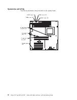


Note:
The illustrations in this document might differ slightly from your hardware.
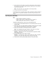
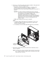
7. Use a flat-blade screwdriver to press up on the lower tab of the control panel
assembly until the bottom of the assembly detaches from the chassis.
8. Press together the two latches at the top of the assembly until it detaches from
the chassis; then, pull the control panel assembly out of the chassis through the
front, making sure that the cables follow freely.
Important:
When removing the assembly, note the routing of the cables
through the aperture in the chassis. You must route the cables
through this aperture upon reinstallation to avoid damage to the
cables when the drive cage is in the closed position.
To install the control panel assembly, reverse the previous steps, making sure to
route the cables carefully and snap the operator information panel into place.
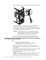
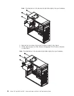
Front USB connector assembly
Note:
v
Read “Installation guidelines” on page 23.
v
Read the safety notices at “Safety information” on page 107.
v
Read “Handling static-sensitive devices” on page 24.
Complete the following steps to remove the front USB connector assembly:
1. Turn off the server and attached devices; then, disconnect all power cords and
external cables.
2. Remove the cover and support bracket (see“Removing the side cover” on page
26 and “Removing and installing the support bracket” on page 28).
3. Remove the front bezel (see “Removing the bezel” on page 27).
4. Rotate the drive cage up.
Attention:
Do not place any strain on the hard disk drive cables; it might be
necessary to disconnect these cables before pivoting the drive cage.
5. Disconnect the front USB connector assembly cable from the system board.
64
xSeries 206 Type 8482 and 8487: Hardware Maintenance Manual and Troubleshooting Guide
Содержание 84875MU
Страница 1: ...xSeries 206 Type 8482 and 8487 Hardware Maintenance Manual and Troubleshooting Guide...
Страница 2: ......
Страница 3: ...xSeries 206 Type 8482 and 8487 Hardware Maintenance Manual and Troubleshooting Guide...
Страница 6: ...iv xSeries 206 Type 8482 and 8487 Hardware Maintenance Manual and Troubleshooting Guide...
Страница 10: ...viii xSeries 206 Type 8482 and 8487 Hardware Maintenance Manual and Troubleshooting Guide...
Страница 22: ...12 xSeries 206 Type 8482 and 8487 Hardware Maintenance Manual and Troubleshooting Guide...
Страница 68: ...58 xSeries 206 Type 8482 and 8487 Hardware Maintenance Manual and Troubleshooting Guide...
Страница 86: ...76 xSeries 206 Type 8482 and 8487 Hardware Maintenance Manual and Troubleshooting Guide...
Страница 127: ...Appendix B Related service information 117...
Страница 128: ...118 xSeries 206 Type 8482 and 8487 Hardware Maintenance Manual and Troubleshooting Guide...
Страница 129: ...Appendix B Related service information 119...
Страница 130: ...120 xSeries 206 Type 8482 and 8487 Hardware Maintenance Manual and Troubleshooting Guide...
Страница 131: ...Appendix B Related service information 121...
Страница 132: ...122 xSeries 206 Type 8482 and 8487 Hardware Maintenance Manual and Troubleshooting Guide...
Страница 133: ...Appendix B Related service information 123...
Страница 143: ...Appendix B Related service information 133...
Страница 144: ...134 xSeries 206 Type 8482 and 8487 Hardware Maintenance Manual and Troubleshooting Guide...
Страница 145: ...Appendix B Related service information 135...
Страница 146: ...136 xSeries 206 Type 8482 and 8487 Hardware Maintenance Manual and Troubleshooting Guide...
Страница 150: ...140 xSeries 206 Type 8482 and 8487 Hardware Maintenance Manual and Troubleshooting Guide...
Страница 159: ......
Страница 160: ...Part Number 49Y0092 Printed in USA 1P P N 49Y0092...


