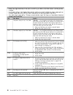
v
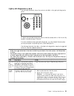
Follow
the
suggested
actions
in
the
order
in
which
they
are
listed
in
the
Action
column
until
the
problem
is
solved.
v
See
the
parts
listing
in
the
Problem
Determination
and
Service
Guide
to
determine
which
components
are
customer
replaceable
units
(CRU)
and
which
components
are
field
replaceable
units
(FRU).
v
If
an
action
step
is
preceded
by
“(Trained
service
technician
only),”
that
step
must
be
performed
only
by
a
trained
service
technician.
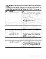
LED
Description
Action
PS
1
The
power
supply
in
bay
1
has
failed.
Attention:
In
a
dc
power
environment,
only
trained
service
personnel
other
than
IBM
service
technicians
are
authorized
to
connect
or
disconnect
power
to
the
dc
power
supply
and
to
remove
and
install
a
dc
power
supply.
See
the
documentation
that
comes
with
each
dc
power
supply.
1.
Make
sure
that
the
power
supply
is
correctly
seated.
2.
Replace
the
failed
power
supply.
PS
2
The
power
supply
in
bay
2
has
failed.
Attention:
In
a
dc
power
environment,
only
trained
service
personnel
other
than
IBM
service
technicians
are
authorized
to
connect
or
disconnect
power
to
the
dc
power
supply
and
to
remove
and
install
a
dc
power
supply.
See
the
documentation
that
comes
with
each
dc
power
supply.
1.
Make
sure
that
the
power
supply
is
correctly
seated.
2.
Replace
the
failed
power
supply.
CPU
A
microprocessor
has
failed.
1.
Make
sure
that
the
failing
microprocessor,
which
is
indicated
by
a
lit
LED
on
the
system
board,
is
installed
correctly.
See
“Installing
a
microprocessor”
on
page
62
for
information
about
installing
a
microprocessor.
2.
Make
sure
that
a
ServeRAID
8k
or
8k-l
SAS
controller
is
installed
and
correctly
seated.
Make
sure
that
the
battery
for
the
ServeRAID
8k
SAS
controller
is
installed
correctly.
3.
Call
for
service.
VRM
An
error
occurred
on
the
microprocessor
voltage
regulator
module
(VRM).
1.
Replace
the
VRM.
2.
Call
for
service.
CNFG
A
hardware
configuration
error
has
occurred.
1.
Check
the
microprocessors
that
were
just
installed
to
make
sure
that
they
are
compatible
with
each
other
and
with
the
VRM
(see
“Installing
a
microprocessor”
on
page
62
for
compatiblity
requirements).
2.
(Trained
service
technician
only)
Replace
an
incompatible
microprocessor.
3.
Check
the
system-error
logs
for
information
about
the
error.
Replace
any
components
that
are
indicated.
MEM
A
memory
error
has
occurred.
Replace
the
failing
DIMM,
which
is
indicated
by
the
lit
LED
on
the
system
board.
NMI
A
machine
check
error
has
occurred.
Check
the
system-error
log
for
information
about
the
error.
S
ERR
Reserved.
26
System
x3650
Type
7979:
User’s
Guide
Содержание 7979B1U
Страница 1: ...System x3650 Type 7979 User s Guide...
Страница 2: ......
Страница 3: ...System x3650 Type 7979 User s Guide...
Страница 8: ...vi System x3650 Type 7979 User s Guide...
Страница 30: ...14 System x3650 Type 7979 User s Guide...
Страница 130: ...114 System x3650 Type 7979 User s Guide...
Страница 138: ...122 System x3650 Type 7979 User s Guide...
Страница 143: ......
Страница 144: ...Part Number 44R5189 Printed in USA 1P P N 44R5189...

