background image

System


x3650


Type


7979

User’s


Guide


Содержание 7979B1U

Страница 1: ...System x3650 Type 7979 User s Guide...

Страница 2: ......

Страница 3: ...System x3650 Type 7979 User s Guide...

Страница 4: ...and the Warranty and Support Information document on the IBM System x Documentation CD Fifth Edition December 2007 Copyright International Business Machines Corporation 2007 All rights reserved US Gov...

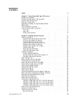
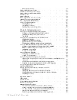
Страница 5: ...rking inside the server with the power on 29 Handling static sensitive devices 30 Removing the cover 31 Removing the riser card assembly 32 Installing the riser card assembly 33 Removing the microproc...

Страница 6: ...95 Configuring the controller 96 Viewing the configuration 96 Using ServeRAID Manager 96 Configuring the RAID controller 97 Viewing the configuration 98 Using the baseboard management controller 98 En...

Страница 7: ...nformance statement 120 Taiwanese Class A warning statement 121 Chinese Class A warning statement 121 Japanese Voluntary Control Council for Interference VCCI statement 121 Korean Class A warning stat...

Страница 8: ...vi System x3650 Type 7979 User s Guide...

Страница 9: ...tuotteen lue turvaohjeet kohdasta Safety Information Avant d installer ce produit lisez les consignes de s curit Vor der Installation dieses Produkts die Sicherheitshinweise lesen Prima di installare...

Страница 10: ...this document before you perform the procedures Read any additional safety information that comes with the server or optional device before you install the device Attention The information in this do...

Страница 11: ...quipment when there is evidence of fire water or structural damage v Disconnect the attached power cords telecommunications systems networks and modems before you open the device covers unless instruc...

Страница 12: ...ning a lithium battery replace it only with the same module type made by the same manufacturer The battery contains lithium and can explode if not properly used handled or disposed of Do not v Throw o...

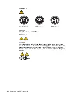
Страница 13: ...he device v Use of controls or adjustments or performance of procedures other than those specified herein might result in hazardous radiation exposure DANGER Some laser products contain an embedded Cl...

Страница 14: ...utton on the device and the power switch on the power supply do not turn off the electrical current supplied to the device The device also might have more than one power cord To remove all electrical...

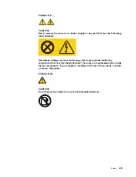
Страница 15: ...s voltage current and energy levels are present inside any component that has this label attached There are no serviceable parts inside these components If you suspect a problem with one of these part...

Страница 16: ...m phase to phase voltage is 240 V under any distribution fault condition Important This product is not suitable for use with visual display workplace devices according to Clause 2 of the German Ordina...

Страница 17: ...3 5 inch models will be used to distinguish between the server styles Performance ease of use reliability and expansion capabilities were key considerations in the design of the server These design f...

Страница 18: ...ding statement in your language in the Safety Information document v Rack Installation Instructions This printed document contains instructions for installing the server in a rack v Problem Determinat...

Страница 19: ...n be potentially lethal or extremely hazardous to you A danger statement is placed just before the description of a potentially lethal or extremely hazardous procedure step or situation Features and s...

Страница 20: ...rt and TCP IP Offload Engine TOE support v One RAID controller active only when a 8k or 8k l SAS controller is installed v One serial port v One serial attached SCSI SAS controller v Seven Universal S...

Страница 21: ...he system configuration and activates a pair of online spare DIMMs For more information see Installing a memory module on page 67 Large system memory capacity The server supports up to 48 GB of system...

Страница 22: ...hem using IBM Director For more information including the required levels of IBM Director and PowerExecutive see the IBM Director documentation on the IBM Director CD or see http www ibm com systems m...

Страница 23: ...atures v Automatic error retry and recovery v Automatic restart after a power failure v Backup basic input output system BIOS switching under the control of the baseboard management controller v Baseb...

Страница 24: ...ft Windows 2000 Server Windows Server 2003 Windows XP Professional AIX i5 OS Red Hat Linux SUSE Linux VMware and Novell NetWare For a complete list of operating systems that support IBM Director see t...

Страница 25: ...mitting diodes LEDs and connectors on the front of the 3 5 inch model server Operator information panel USB 5 connector USB 6 connector Video connector Rack release latch Rack release latch CD DVD dri...

Страница 26: ...among other servers You can use IBM Director to light this LED remotely v Information LED When this LED is lit it indicates that a noncritical event has occurred An LED on the light path diagnostics p...

Страница 27: ...er supply AC power LED Each hot swap power supply has an ac power LED and a dc power LED When the ac power LED is lit it indicates that sufficient power is coming into the power supply through the pow...

Страница 28: ...of the shared serial port to perform text console redirection and to redirect serial traffic using Serial over LAN SOL SAS connector Connect a serial attached SCSI SAS device to this connector Server...

Страница 29: ...t turn off the electrical current supplied to the device The device also might have more than one power cord To remove all electrical current from the device ensure that all power cords are disconnect...

Страница 30: ...14 System x3650 Type 7979 User s Guide...

Страница 31: ...your hardware Cover Power supply filler Power supply Power backplane 2 5 inch drive cage with hard disk drive backplane 2 5 inch hard disk drive 2 5 inch filler panel 3 5 inch cage divider 3 5 inch h...

Страница 32: ...apter Low profile adapter Remote Supervisor Adapter II SlimLine DIMM air baffle DIMM ServeRAID SAS controller System board VRM Heat sink filler Heat sink Microprocessor Heat sink retention module 16 S...

Страница 33: ...II SlimLine connector PCI Express slot 4 connector PCI Express slot 3 connector Battery connector Microprocessor 1 connector Microprocessor 2 connector Voltage regulator module connector DIMM 10 conn...

Страница 34: ...clarity in the following illustration the PCI riser card assembly is inverted PCI adapter connectors Power backplane board connectors The following illustration shows the internal connectors on the po...

Страница 35: ...ctors on the system board Hard disk drive backplane signal J92 Power backplane J72 Tape drive power J100 Front USB J80 Front video J51 Internal USB J82 CD DVD signal J37 CD DVD power J12 Operator pane...

Страница 36: ...ectors The following illustration shows the external input output connectors on the system board USB 1 USB 2 Ethernet 2 USB 3 Ethernet 1 USB 4 Video Serial Systems management Ethernet SAS 20 System x3...

Страница 37: ...section about recovering the basic input output system BIOS code in the Problem Determination and Service Guide on the IBM System x Documentation CD for information about using the boot block recover...

Страница 38: ...n password 4 Off Reserved 3 Off Reserved 2 Off Reserved 1 Off Clear CMOS When this switch is toggled to On it clears the CMOS data which clears the power on password Important 1 Before you change any...

Страница 39: ...DIMM 7 error LED DIMM 8 error LED DIMM 9 error LED DIMM 12 error LED DIMM 11 error LED DIMM 10 error LED VRM error LED Power channel B error LED Power channel A error LED Power channel D error LED Pow...

Страница 40: ...Riser card assembly LEDs The following illustration shows the light emitting diodes LEDs on the riser card assembly PCI Slot 1 error LED PCI Slot 2 error LED 24 System x3650 Type 7979 User s Guide...

Страница 41: ...nents are customer replaceable units CRU and which components are field replaceable units FRU v If an action step is preceded by Trained service technician only that step must be performed only by a t...

Страница 42: ...mes with each dc power supply 1 Make sure that the power supply is correctly seated 2 Replace the failed power supply CPU A microprocessor has failed 1 Make sure that the failing microprocessor which...

Страница 43: ...RAID controller is installed Note The server will not start without a RAID controller installed 2 Check the system error log for information about the error FAN A fan has failed is operating too slowl...

Страница 44: ...ion CD for diagnostic information v Observe good housekeeping in the area where you are working Place removed covers and other parts in a safe place v If you must start the server while the cover is r...

Страница 45: ...supply v There is adequate space around the server to allow the server cooling system to work properly Leave approximately 50 mm 2 0 in of open space around the front and rear of the server Do not pl...

Страница 46: ...wear an electrostatic discharge wrist strap if one is available Always use an electrostatic discharge wrist strap or other grounding system when working inside the server with the power on v Handle t...

Страница 47: ...er battery or other non hot swap optional device turn off the server and all attached devices and disconnect all external cables and power cords see Turning off the server on page 13 Attention In a dc...

Страница 48: ...safety information that begins on page vii and Installation guidelines on page 28 2 Turn off the server and peripheral devices and disconnect the power cord and all external cables Attention In a dc...

Страница 49: ...tall any adapters and reconnect any internal cables that you removed in other procedures 4 Carefully align the riser card assembly with the release tab posts the guides on the rear of the server and t...

Страница 50: ...nly trained service personnel other than IBM service technicians are authorized to connect or disconnect power to the dc power supply See the documentation that comes with each dc power supply 3 Remov...

Страница 51: ...service personnel other than IBM service technicians are authorized to connect or disconnect power to the dc power supply See the documentation that comes with each dc power supply 3 Remove the cover...

Страница 52: ...g off the server on page 13 Attention In a dc power environment only trained service personnel other than IBM service technicians are authorized to connect or disconnect power to the dc power supply S...

Страница 53: ...icians are authorized to connect or disconnect power to the dc power supply See the documentation that comes with each dc power supply 3 Remove the cover see Removing the cover on page 31 4 Align the...

Страница 54: ...n slot 2 on the PCI riser card and a full height full length adapter in slot 1 on the PCI riser card v An optional Remote Supervisor Adapter II SlimLine can be installed only in a dedicated slot on th...

Страница 55: ...pter connectors To install an adapter complete the following steps 1 Read the safety information that begins on page vii and Installation guidelines on page 28 2 Turn off the server and peripheral dev...

Страница 56: ...PCI slot Note For clarity the riser card assembly is shown inverted in the following illustration Inverted riser assembly 8 If you removed the PCI riser card assembly to install the adapter align the...

Страница 57: ...v Make sure that cables are not routed on top of components under the PCI riser card assembly v Make sure that cables are not pinched by the server components 10 Perform any configuration tasks that...

Страница 58: ...all power cords and external cables see Turning off the server on page 13 Attention In a dc power environment only trained service personnel other than IBM service technicians are authorized to conne...

Страница 59: ...rvisor Adapter II SlimLine can be installed only in a dedicated slot on the system board See System board optional device connectors on page 17 for the location of the connector After the Remote Super...

Страница 60: ...Turn the Remote Supervisor Adapter II SlimLine so that the keys on the connector align correctly with the connector on the system board 6 Slip the free end of the Remote Supervisor Adapter II SlimLin...

Страница 61: ...n In a dc power environment only trained service personnel other than IBM service technicians are authorized to connect or disconnect power to the dc power supply See the documentation that comes with...

Страница 62: ...rized to connect or disconnect power to the dc power supply See the documentation that comes with each dc power supply 3 Remove the cover see Removing the cover on page 31 4 Remove the riser card asse...

Страница 63: ...after which the startup process continues This is a one time occurrence Important You must allow the initialization process to be completed If you do not the battery pack will not work and the server...

Страница 64: ...peed v The ID that is assigned to each bay is printed on the front of the server The following illustrations show how to install a hot swap hard disk drive 3 5 inch drives Filler panel Hard disk drive...

Страница 65: ...ed position e Check the hard disk drive status LED to verify that the hard disk drive is operating correctly If the amber hard disk drive status LED for a drive is lit continuously that drive is fault...

Страница 66: ...ve other optional devices to install or remove do so now Otherwise go to Completing the installation on page 81 Installing an optional tape drive Prepare the drive according to the instructions that c...

Страница 67: ...it to the tape drive assembly do so now 7 From the inside of the server thread the tape drive end of the cables through the slot in the left side of the hard disk drive cage and out the front of the s...

Страница 68: ...connector SATA tape cable 12 Install the fan bracket assembly If you have other optional devices to install or remove do so now Otherwise go to Completing the installation on page 81 52 System x3650...

Страница 69: ...emove the filler panel from the tape drive bay 7 From the inside of the server thread the tape drive end of the cables for your tape drive through the rear of the tape drive bay and out the front of t...

Страница 70: ...nd to connect the tape drive to a supported SCSI adapter in PCI slot 1 of the riser card assembly See http www ibm com servers eserver serverproven compat us for the list of supported SCSI tape drives...

Страница 71: ...al devices and disconnect the power cords and all external cables Attention In a dc power environment only trained service personnel other than IBM service technicians are authorized to connect or dis...

Страница 72: ...s shown in the following illustration and press the terminator onto the top of the CD DVD drive bay SCSI terminator 12 Remove the riser card assembly and the DIMM air baffle see Removing the riser car...

Страница 73: ...ble clamp 17 Reconnect the hard disk drive backplane signal cable to the connector on the system board 18 Reinstall the DIMM air baffle Make sure that it clicks into place You might have to apply extr...

Страница 74: ...pe drive such as the IBM DDS Generation 5 Internal Tape Drive and to connect the tape drive to a supported SCSI adapter in PCI slot 1 of the riser card assembly See http www ibm com servers eserver se...

Страница 75: ...of the tape drive 10 Thread the cables through the tape drive bay toward the server 11 Push the tape drive assembly into the tape drive bay gently pulling the cables farther out the back of the bay a...

Страница 76: ...llustration Make sure that the cable passes through the cable clamp Important Make sure that the cables avoid any fan connectors SCSI signal cable Cable clamp 19 Connect the tape drive power cable to...

Страница 77: ...e do so now Otherwise go to Completing the installation on page 81 Removing an optional tape drive The following illustration shows how to remove an optional tape drive from a 3 5 inch server model To...

Страница 78: ...the side of the bay If the drive is a SCSI drive disconnect the SCSI cable from the rear of the tape drive and gently pull it back through the slot and into the server then lift the cable out of the s...

Страница 79: ...oftware and device drivers 4 Click System x3650 to display the matrix of downloadable files for the server v Optional Obtain an SMP capable operating system For a list of supported operating systems a...

Страница 80: ...be identical To install an additional microprocessor complete the following steps 1 Read the safety information that begins on page vii and Installation guidelines on page 28 2 Turn off the server an...

Страница 81: ...te the second microprocessor connector on the system board 7 Rotate the heat sink release lever to the fully open position 8 Lift the heat sink filler out of the server 9 Install the microprocessor a...

Страница 82: ...th the socket note the alignment mark and the position of the notches then carefully place the microprocessor on the socket Close the microprocessor bracket frame Note The microprocessor fits only one...

Страница 83: ...information that you must consider when installing DIMMs v The server supports up to 12 Fully Buffered DIMM PC2 5300 512 MB 1 GB 2 GB and 4 GB DIMMs for a maximum of 48 GB of system memory See http w...

Страница 84: ...itches from the active pair to the mirroring pair See Memory mirroring on page 69 for more information about memory mirroring and the DIMM installation sequence that is required v The server supports...

Страница 85: ...urn the DIMM so that the DIMM keys align correctly with the connector 9 Insert the DIMM into the connector by aligning the edges of the DIMM with the slots at the ends of the DIMM connector Firmly pre...

Страница 86: ...able online spare memory through the Configuration Setup Utility program The BIOS code assigns the online spare DIMM pairs according to your DIMM configuration Online sparing is enabled on a memory br...

Страница 87: ...paring on branch 1 12 1 and 4 largest DIMMs 2 and 5 3 and 6 7 and 10 8 and 11 9 and 12 Online sparing on branch 0 Online sparing on branch 1 Table 7 Online spare DIMM configurations alternative scheme...

Страница 88: ...en the retaining clip on each end of the DIMM connector 7 Lift the DIMM out of the connector 8 Replace the DIMM or remove the second DIMM of the pair If you have other optional devices to install or r...

Страница 89: ...ese components If you suspect a problem with one of these parts contact a service technician Power supply filler release lever Power supply filler Hot swap power supply 2 To install an ac power supply...

Страница 90: ...o connect or disconnect power to the dc power supply See the documentation that comes with each dc power supply for installation instructions The following illustration shows the ac power supply conne...

Страница 91: ...old it down 5 Pull the power supply part of the way out of the bay 6 Release the release latch then support the power supply and pull it the rest of the way out of the bay If you have other optional d...

Страница 92: ...new fan over its position in the fan assembly bracket so that the LED on top of the fan is toward the left side of the server 4 Push the new fan into the fan assembly bracket until it clicks into pla...

Страница 93: ...ull the handles toward each other and lift the fan out of the server 5 Replace the fan as soon as possible see Installing a fan on page 75 If you have other optional devices to install or remove do so...

Страница 94: ...ment only trained service personnel other than IBM service technicians are authorized to connect or disconnect power to the dc power supply See the documentation that comes with each dc power supply 3...

Страница 95: ...ect or disconnect power to the dc power supply See the documentation that comes with each dc power supply 3 Align the guides on the left and right sides of the assembly with the slots in the sides of...

Страница 96: ...cumentation that comes with each dc power supply 3 Remove the cover see Removing the cover on page 31 4 Press the release tab down to release the drive then while pressing the tab push the drive towar...

Страница 97: ...nstallation Completing the installation To complete the installation complete the following steps 1 If you removed the PCI riser card assembly replace the riser card assembly see Installing the riser...

Страница 98: ...lease latch To install the cover complete the following steps 1 Place the cover release latch in the open up position 2 Insert the bottom tabs of the top cover into the matching slots in the server ch...

Страница 99: ...omes with the operating system for additional cabling instructions Updating the server configuration When you start the server for the first time after you add or remove an internal device external SA...

Страница 100: ...Supervisor Adapter User s Guide which comes with the adapter for information about setting up configuring and using the adapter For information about configuring the integrated Gigabit Ethernet contr...

Страница 101: ...y subsystem before you install the operating system For information about using this program see Using ServeRAID Manager on page 96 v Ethernet controller configuration For information about configurin...

Страница 102: ...ode some menu choices might differ slightly from these descriptions v System Summary Select this choice to view configuration information including the ID speed and cache size of the microprocessors a...

Страница 103: ...age 91 Power on Password Select this choice to set or change a power on password See Power on password on page 90 for more information v Start Options Select this choice to view or change the start op...

Страница 104: ...ected to the slot RSA II Settings This choice is available only if an optional Remote Supervisor Adapter II SlimLine is installed Select this choice to configure the settings for the Remote Supervisor...

Страница 105: ...elect this choice to view the BMC system event log which contains messages about system events such as devices inserted or removed or a threshold reached Select Clear BMC SEL to clear the BMC system e...

Страница 106: ...p but you must type the administrator password to access the Configuration Setup Utility menu If you set a power on password for a user and an administrator password for a system administrator you can...

Страница 107: ...personnel other than IBM service technicians are authorized to connect or disconnect power to the dc power supply See the documentation that comes with each dc power supply Administrator password If a...

Страница 108: ...power supply 3 Remove the server from the rack and place it on a flat static protective surface 4 Remove the cover See Removing the cover on page 31 for instructions 5 Move the clear CMOS switch switc...

Страница 109: ...em automatically If a later version of the ServerGuide program is available you can download a free image of the ServerGuide Setup and Installation CD or you can purchase the CD To download the image...

Страница 110: ...erGuide features v View the readme file to review installation tips for your operating system and adapter v Start the operating system installation You will need your operating system CD Typical opera...

Страница 111: ...programs to configure and manage arrays consider the following information v Hard disk drive capacities affect how you create arrays Drives in an array can have different capacities but the RAID cont...

Страница 112: ...or the array 8 When you are prompted for the array build method select Quick Init 9 Follow the instructions on the screen to complete the configuration then select Done to exit 10 Restart the server V...

Страница 113: ...n the ServeRAID Manager tree into an array and creating a RAID level 1 logical drive If you select custom configuration you can select the two physical drives that you want to group into an array and...

Страница 114: ...ote server management capabilities through the OSA SMBridge management utility program v Command line interface IPMI Shell The command line interface provides direct access to server management functi...

Страница 115: ...nabled v Remote Console Flow Control Hardware d Press Esc twice to exit the Remote Console Redirection and Devices and I O Ports sections of the Configuration Setup Utility program e Select Advanced S...

Страница 116: ...rough the SOL console ttyS0 LILO configuration If you are using LILO complete the following steps 1 Modify the etc lilo conf file a Add the following text to the end of the first default linux line Mo...

Страница 117: ...stall boot boot b message boot message linear image boot vmlinuz 2 4 9 e 12smp label linux initrd boot initrd 2 4 9 e 12smp img read only root dev hda6 image boot vmlinuz 2 4 9 e 12 label linux up ini...

Страница 118: ...g system starts a LILO boot prompt is displayed instead of the graphical user interface Press Tab at this prompt to install all of the boot options that are listed To load the operating system in inte...

Страница 119: ...o not have to rerun grub after making changes to this file NOTICE You have a boot partition This means that all kernel and initrd paths are relative to boot eg root hd0 0 kernel vmlinuz version ro roo...

Страница 120: ...4 9 e 12 ro root dev hda6 initrd initrd 2 4 9 e 12 img You must restart the Linux operating system after you complete these procedures for the changes to take effect and to enable SOL SUSE SLES 9 0 c...

Страница 121: ...lor white blue black light gray default 0 timeout 8 title linux kernel hd0 1 boot vmlinuz root dev hda2 acpi oldboot vga 791 1 initrd hd0 1 boot initrd title floppy root chainloader 1 title failsafe k...

Страница 122: ...mpt then press Enter to display the current boot options for your server b In the Boot Entries section locate the boot entry ID for the section with an OS friendly name of Windows Server 2003 Standard...

Страница 123: ...t You must restart the Windows 2003 operating system after you complete this procedure for the changes to take effect and to enable SOL Installing the OSA SMBridge management utility program Important...

Страница 124: ...steps You must be logged in as a root user to perform these procedures 1 Go to http www ibm com systems support Download the utility program and create the OSA BMC Management Utility CD 2 Insert the O...

Страница 125: ...ne prompt type bmc_cfg and press Enter 3 Follow the instructions on the screen Using the baseboard management controller firmware update utility program Use the baseboard management controller firmwar...

Страница 126: ...and off remotely reboot Force the server to restart sel get Display the BMC system event log sol Configure the SOL function sysinfo Display system information that is related to the server and the gl...

Страница 127: ...M Director than what comes with the server follow the instructions on the Web page to download the latest version 2 Install IBM Director 3 Download and install any applicable updates or interim fixes...

Страница 128: ...onal information about network configuration see the Remote Supervisor Adapter II Installation Guide To cable the Remote Supervisor Adapter II SlimLine complete the following steps 1 Connect one end o...

Страница 129: ...tation CD for instructions for completing the configuration including the following procedures v Configuring the Ethernet ports v Defining login IDs and passwords v Selecting the events that will rece...

Страница 130: ...114 System x3650 Type 7979 User s Guide...

Страница 131: ...UDING BUT NOT LIMITED TO THE IMPLIED WARRANTIES OF NON INFRINGEMENT MERCHANTABILITY OR FITNESS FOR A PARTICULAR PURPOSE Some states do not allow disclaimer of express or implied warranties in certain...

Страница 132: ...marks of Red Hat Inc in the United States and other countries Other company product or service names may be trademarks or service marks of others Important notes Processor speed indicates the internal...

Страница 133: ...found on IBM s Internet site at http www ibm com ibm environment products index shtml Esta unidad debe reciclarse o desecharse de acuerdo con lo establecido en la normativa nacional o local aplicable...

Страница 134: ...any potential effects of EEE on the environment and human health due to the potential presence of hazardous substances in EEE For proper collection and treatment contact your local IBM representative...

Страница 135: ...cerned in the battery Pb for lead Hg for mercury and Cd for cadmium Users of batteries and accumulators must not dispose of batteries and accumulators as unsorted municipal waste but use the collectio...

Страница 136: ...product may cause radio interference in which case the user may be required to take adequate measures United Kingdom telecommunications safety requirement Notice to Customers This apparatus is approve...

Страница 137: ...0049 0 711 785 1283 E mail tjahn de ibm com Taiwanese Class A warning statement Chinese Class A warning statement Japanese Voluntary Control Council for Interference VCCI statement Korean Class A warn...

Страница 138: ...122 System x3650 Type 7979 User s Guide...

Страница 139: ...lass A electronic emission notice 119 clear CMOS 91 clear CMOS switch 91 command line interface commands identify 110 power 110 sel 110 sysinfo 110 command line interface continued for remote manageme...

Страница 140: ...microprocessor 62 power supply 72 RAID controller 46 Remote Supervisor Adapter II SlimLine 43 tape drive 50 VRM 65 J jumper clear CMOS password override 91 jumpers 21 L LEDs 11 Ethernet activity 11 E...

Страница 141: ...nnector 12 serial over LAN commands connect 110 identify 110 serial over LAN continued commands continued power 110 reboot 110 sel get 110 sol 110 sysinfo 110 ServeRAID 6 ServeRAID Manager 96 ServerGu...

Страница 142: ...t controller utility programs 109 utility program Configuration Setup 86 IBM ServeRAID Configuration 95 V video connector front 10 rear 12 voltage regulator module installing 65 VRM See voltage regula...

Страница 143: ......

Страница 144: ...Part Number 44R5189 Printed in USA 1P P N 44R5189...

Отзывы: