


PfofiBus Gateway
6 Communication
Signal
Details
6.1 Overview of Communication Signal Timings
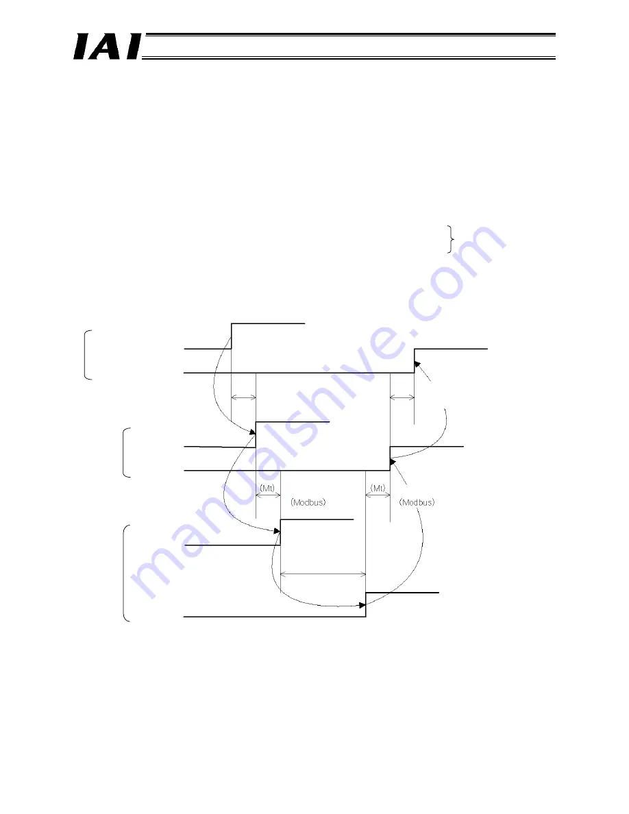
When a given control signal is turned ON to operate the ROBO Cylinder using the sequence program in
the PLC, the maximum response time before a response (status) signal will be received is expressed by
the formula below:
Maximum response time (msec) = Yt + Xt + 2 x Mt = Command processing time (operation time, etc.)
Mt = 10 (msec) x (n+1): SIO link (Modbus) cycle time
n: Number of controlled axes
Yt: Master
→
remote I/O station transmission delay
ProfiBus
transmission delay
Xt: Remote I/O
→
master station transmission delay
For the master
→
remote I/O station transmission delay (Yt) and remote I/O
→
master station
transmission delay (Xt), refer to the operation manuals for your ProfiBus master unit and PLC.
PLC sequence program
Control signal
Status signal
Master
→
remote I/O station
transmission delay (Yt)
Remote I/O
→
master station
transmission delay (Xt)
Gateway
Control signal
Status signal
Controller
Control signal
Status signal
SIO link cycle time
SIO link cycle time
Response
processing time
(Note) If a communication error occurs due to a problem along the transmission path, etc.,
a communication retry or retries (up to three times) may occur, in which case the SIO link cycle
time (Mt) will be extended.
75
Содержание RCM-GW-PR
Страница 1: ...Operation Manual Second Edition ProfiBus Gateway Unit RCM GW PR ...
Страница 6: ......
Страница 15: ...PfofiBus Gateway 2 2 External Dimensions Dimensions Installed dimension 9 ...
Страница 82: ...PfofiBus Gateway 76 ...


