background image

www.i2systems.com

Integrated Illumination Systems, Inc.

355 Bantam Lake Road
Morris, CT  06763 USA 

tel +1.860.567.0708
fax +1.860.567.2501
[email protected]

Product information is subject to change without notice.
All brand names and product names are trademarks of i2Systems.
© 2012 i2Systems. All Rights Reserved.

Gen3


Installation Guide

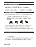
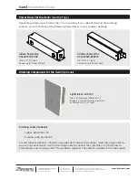
Use only wet location Fixtures for exterior applications.

Fixtures marked with an “I” are intended for indoor use only. They should not be used for  
exterior applications. 

You must install and operate all i2Systems Fixtures within the recommended temperature and 
environmental ratings.


•  Fixtures rated for exterior applications are not rated for submersible use.  


  You should not mount the Fixture in a location that has or may have standing water.


•  You should never install a Fixture where there is or may be moving water from runoff  


  or downspouts.

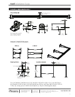
i2Systems offers two options when ordering the Gen3:


•  Hardwire (Standard)


•  Plug-Together (Optional)

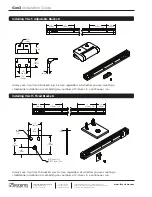
If you are installing a Gen3 Fixture equipped with the connector Plug-Together option, make sure 
all connector plugs are fully seated during the installation process. For the last Fixture in any run, 
use End Plug Model 720-02050 to cap any unused connector. Failure to do so may result in  
intermittent connection, corrosion, and/or leakage in the main housing.

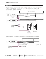
It is good practice to seal all Fixtures and junction boxes with electronics-grade RTV silicone  
sealant. This will ensure that moisture cannot enter or accumulate in wiring compartments, 
cables, or other electrical parts when you install the Fixture in wet or damp locations.

You should also install a loop into the cable at the Fixture end to prevent water from wicking into 
the Fixture. Inspect the cable after installation to ensure that the cable covering will remain intact 
and there will be no chafing, pulling, or cutting that could leak water into the Fixture.

  Wet Location/Outdoor Use Fixture Labeling

  Outdoor Installation Considerations

  Wet Location Connection Considerations

V3285A-16AAG I

V3285A-16AAG

6

Содержание Gen3 V3285

Страница 1: ...Gen3 V3285 Installation Guide ...

Страница 2: ... Illumination Systems Inc 355 Bantam Lake Road Morris CT 06763 USA tel 1 860 567 0708 fax 1 860 567 2501 sales i2systems com Product information is subject to change without notice All brand names and product names are trademarks of i2Systems 2012 i2Systems All Rights Reserved ...

Страница 3: ...60 567 0708 or email at support i2systems com A free copy of this installation guide is available online at www i2systems com along with these resources Gen3 Spec Sheet LightLink LL 205 Installation Guide Power Box PS24V75W E05P E05PW Datasheet Copyright 2012 i2Systems All Rights Reserved Support Copyright i2Systems the i2Systems Logo Gen3 and LightLink are either registered trademarks or trademar...

Страница 4: ...ician should install i2Systems products While it may be tempting to skip sections we assure you that reading this material will help you to avoid problems and speed up the installation process Introduction 3 Pick an accessible area that allows for future maintenance and or service of the Fixture Review the temperature and environmental conditions to ensure the Fixture operates within recommended r...

Страница 5: ...ndividual units Follow all national and local electrical and construction codes and regulations Avoid all temptation to disassemble the Fixture because there are no serviceable parts and tampering with it could cause shock Use only Fixtures marked for exterior use in outdoor applications Comply with the maximum voltage rating of the Fixture Operate the Fixture within the specified temperature and ...

Страница 6: ... point on the housing at worst case ambient temperature The Fixture has i2Systems Active Thermal Management ATM which will reduce power and therefore the case temperature if the Fixture overheats However you should not rely on ATM to regulate temperature as part of the normal operation of the Fixture Failure to operate the Fixture within specified operating and case temperature guidelines will voi...

Страница 7: ...the Gen3 Hardwire Standard Plug Together Optional If you are installing a Gen3 Fixture equipped with the connector Plug Together option make sure all connector plugs are fully seated during the installation process For the last Fixture in any run use End Plug Model 720 02050 to cap any unused connector Failure to do so may result in intermittent connection corrosion and or leakage in the main hous...

Страница 8: ...roduct package Depending how your Fixture was specified during the ordering process you will find one of the following bracket types in your product package Gen3 Specifications Gen3 Mounting Brackets Use One Type Watts 8W per Foot Input Voltage 20 30V DC 24V DC Nominal Operating Temp 20 C to 40 C Max Case Temp Tc 50 C Humidity 0 to 95 Non Condensing Light Output Lumens Watts Color Accuracy CRI 940...

Страница 9: ... sink or source 120 277V AC Input Outdoor Power Box PS24V75W E05PW 120V 277V AC Input Powers up to 10 Feet of Gen3 Depending where you will install the Fixture and how it was specified during the ordering process you will find one of the following Power Boxes in your product package Dimming Cable Optional Indoor 685 01561 100 Outdoor 685 02026 100 For dimming installations i2Systems provides both ...

Страница 10: ...d 1 Per Continuous Run 15 Ft 685 02046 15 Extension Cables Optional 1 Ft 685 02048 1 3 Ft 685 02048 3 15 Ft 685 02048 15 Select the bracket appropriate for your installation Use one of the adjustable brackets VLA 14 or VLA 5 to set the angle at which the light washes or grazes over a wall and ensures the ability to change this angle in the future The use of the VLAX2 6 or VLAX2 12 offers similar p...

Страница 11: ...use one bracket per Fixture until you reach the last Fixture in the run where you will install two brackets as shown in the diagram above Installing Adjustable Brackets VLA 14 Bracket VLAX2 6 VLAX2 12 Brackets VLAX2 6 VLAX2 12 Installation Example Mounting Pattern 88 22mm 1 50 38mm 1 38 35mm 13 3mm 19 5mm 1 25 32mm 75 19mm 20 5mm 23 6mm 59 15mm 6 63 168mm 12 63 321mm 12 00 305mm 6 00 153mm 2 25 57...

Страница 12: ... 29mm 1 8 46mm 1 6 40mm 3 76mm 3 76mm Typ Typ 65 16mm 1 50 38mm 13 3mm 1 25 32mm 50 13mm 11 Always use two VLA 15 brackets per Fixture regardless of whether you are creating a standalone installation or combining any number of Fixtures in a continuous run Installing VLA 5 Adjustable Brackets 1 8 46mm 3 76mm 3 76mm Typ Typ Ø 18 4mm 98 25mm 98 25mm 70 18mm 1 50 38mm 12 3mm 1 6 40mm Installing VLA 15...

Страница 13: ...g Cable From LL 205 Dimming Cable optional Dimming Cable optional Dimming Cable optional LL 205 10V System Layout 12 The diagram below illustrates a basic system installation using the hardwire Fixture configuration with dimming functionality If your installation does not require dimming omit the LL 205 dimming cables and third party dimmer Max Distance 50 Feet using 16 AWG wire Max Load 10 Feet o...

Страница 14: ...Fixtures or Power Boxes that the LL 205 Dimmer will dim however the distance between the LL 205 Dimmer and the last Power Box should never exceed 1000 feet of Dimming Cable Depending on the installation exceeding this limit may cause flicker and or reduce dimming performance When using 0 10V control for large installations multiple LightLink LL 205s may be connected to the same 0 10V signal All Fi...

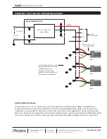
Страница 15: ...ustry practices Alternatively tie the Dim wires together as shown to enable turn on Synchronization as detailed below 100W UL Listed Class 2 Power Supply Synchronizing Fixtures The Gen3 Fixtures are smart fixtures that synchronize and start simultaneously when power is applied to one or more Power Boxes For dimming installations this feature is enabled automatically However for non dimming install...

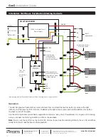
Страница 16: ...ndicator shows selected dim levels Connect Dimming Cable Drain Wire to the LL 205 10V and Power Box Earth Ground LL 205 10V VIO BRN Indoor Dimming Cable uses Red and Black Conductors Outdoor Dimming Cable uses Orange and Violet Operation The LED bar graph will indicate the current dim level Press and hold the top Dim button to increase the light intensity and tap twice for 100 intensity To decreas...

Страница 17: ...onductors Outdoor Dimming Cable uses Orange and Violet ORN RED Dim Up and Down buttons for Manual Dimming LED bar graph indicator shows selected dim levels Connect Dimming Cable Drain Wire to the LL 205 10V and Power Box Earth Ground GRN YEL LL 205 10V Operation The LED bar graph will indicate the current dim level based on 0 to 10V levels The LL 205 10V reads these levels and translates them to i...

Страница 18: ...as Class 2 will void the Fixture s UL safety listing Any damage or reduced performance caused by a third party power supply will void the Gen3 warranty Q For installations without dimming what do I do with the green and white wires on the Gen3 A The white and green wires on the Gen3 are for isolated dimming control White is positive Dim and green is negative Dim These wires are optically isolated ...

Страница 19: ...rd code or instructions for use including those contained in the latest National Electrical Code the Standards for Safety of Underwriters Laboratory Inc the Standards for the American National Standards Institute or in Canada the Canadian Standards Association This Warranty shall become void in the event any repairs or alternations not duly authorized by i2Systems in writing are made to the Produc...

Страница 20: ......
Отзывы: