G8 CPCI Enclosure User’s Guide
2-2
Add-in boards
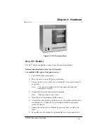
All add-in board modules are mounted through the front of the enclosure.
They are held in place with two injector/ejector handles that stabilize the
boards when they are engaged.
Removal and installation of add-in boards
1. Turn off the main system power.
2. Place the chassis on an ESD safe workstation.
3.
Retract the injector/ejector handles of the add-in board module.
4.
Slide the add-in board module out of the chassis.
5.
Using the module guides, slide the new add-in board into the chassis,
making sure to align the two guide pins with their card guides inside
the chassis.
6.
Engage the injector/ejector handles by pressing them towards each
other.
Note:
If you do not plan on immediately replacing a removed add-
in board, you must close the space left open with a filler
panel in order to maintain EMI specifications.
Chapter 2 - Hardware
Содержание G8
Страница 1: ...G8 CPCI Enclosure User s Guide G8 8 Slot CompactPCI Enclosure User s Guide 095 30004 00 Rev A ...
Страница 8: ...iv Table of Contents This page was intentionally left blank G8 CPCI Enclosure User s Guide ...
Страница 12: ...1 4 Chapter 1 Introduction G8 CPCI Enclosure User s Guide This page was intentionally left blank ...
Страница 20: ...2 8 G8 CPCI Enclosure User s Guide Chapter 2 Hardware This page was intentionally left blank ...
Страница 26: ...4 4 This page was intentionally left blank Chapter 4 Drive Bays G8 CPCI Enclosure User s Guide ...


