


G8 CPCI Enclosure User’s Guide
3-1
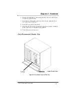
Chapter 3 - Power Distribution
This chapter discusses the power supply, power switch, and input
circuit breaker, and provides installation and removal instructions for each.
CAUTION!
Unless working with hot-swap components, always turn OFF all power and
disconnect the power cords before working on the system.
Power Supplies
The power supplies are available in 350W, current sharing, AC or DC input.
One of the power supplies may be removed and replaced with the system
power on without interrupting the system, provided the remaining supply is
sufficient to power all of the CPU and add-in cards installed in the system.
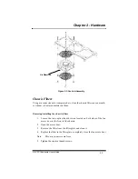
Removing and installing the power supply module
1.
Loosen the two screws on the power supply module’s front panel as
much as possible.
Note:
The screws are captive to the front panel and cannot be complete-
ly removed.
2.
Completely retract the injector/ejector handles
Note:
This may require some force.
3.
Slide the power supply module out of the chassis.
4.
Slide the replacement power supply module into the chassis, making
sure to align the guide pins their card guides.
5.
Engage the injector/ejector handles by pressing them toward each
other.
6.
Secure the power supply module by tightening the two front panel
screws.
Содержание G8
Страница 1: ...G8 CPCI Enclosure User s Guide G8 8 Slot CompactPCI Enclosure User s Guide 095 30004 00 Rev A ...
Страница 8: ...iv Table of Contents This page was intentionally left blank G8 CPCI Enclosure User s Guide ...
Страница 12: ...1 4 Chapter 1 Introduction G8 CPCI Enclosure User s Guide This page was intentionally left blank ...
Страница 20: ...2 8 G8 CPCI Enclosure User s Guide Chapter 2 Hardware This page was intentionally left blank ...
Страница 26: ...4 4 This page was intentionally left blank Chapter 4 Drive Bays G8 CPCI Enclosure User s Guide ...


