Appendix 1 - Technical Reference
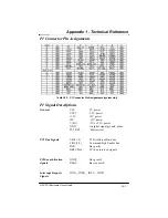
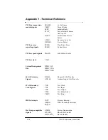
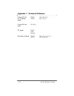
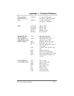
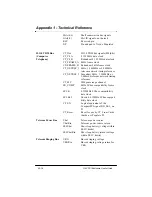
Universal Serial
(+) signal of differential
Bus (USB
)
(0 & 1),
data pair for USB channel
USB
levels
UDATAn-
(-) signal of differential
data pair for USBchannel
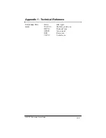
LED's
LANACT1
Ethernet LED
LANLNK1
Ethernet LED
LANSPD1
Ethernet LED
HD ACT
Hard Drive LED
RSVAUX
Reserved LED
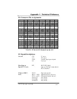
Parallel LPT Port,
ACK_
pulsed by peripheral to
TTL levels (note
acknowledge data sent
some signals are re-
BUSY
Indicates that the printer
defined when used in
cannot accept more data
EPP.ECP modes)
ERR_
Peripheral detected an error
PD[7:0]
Parallel data lines, bits 7--0
PE
Paper end, indicates the printer is
out of paper
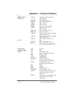
AFD_
Auto feed, causes printer to line
feed
INIT_
Initializes the printer
SLIN_
Select in, selects the printer
STB_
Data strobe, indicates data is valid
SLCT
Select, peripheral indicates it is
selected
Serial COM Ports
CTS
Clear to send
(a & b), RS232 levels
DCD
Data carrier detected
DSR
Data set ready
DTR
Data terminal ready
RI
Ring indicator
RTS
Request to send
RXD
Serial receive data
TXD
Serial transmit data
A1-11
G8 CPCI Enclosure User’s Guide
Содержание G8
Страница 1: ...G8 CPCI Enclosure User s Guide G8 8 Slot CompactPCI Enclosure User s Guide 095 30004 00 Rev A ...
Страница 8: ...iv Table of Contents This page was intentionally left blank G8 CPCI Enclosure User s Guide ...
Страница 12: ...1 4 Chapter 1 Introduction G8 CPCI Enclosure User s Guide This page was intentionally left blank ...
Страница 20: ...2 8 G8 CPCI Enclosure User s Guide Chapter 2 Hardware This page was intentionally left blank ...
Страница 26: ...4 4 This page was intentionally left blank Chapter 4 Drive Bays G8 CPCI Enclosure User s Guide ...

