


PG 3.2
BL
BL
BL
BL
BLADE CHANGING PROCEDURE,
ADE CHANGING PROCEDURE,
ADE CHANGING PROCEDURE,
ADE CHANGING PROCEDURE,
ADE CHANGING PROCEDURE,
CONTINUED
CONTINUED
CONTINUED
CONTINUED
CONTINUED
5. Before installing the new blade, check that it measures 1.075" wide including the teeth. Some
blade manufacturers supply blades that measure 1" including the teeth. In this case you may not be
able to adjust the head down limit switch to complete the cut.
6. Your new blade will be in a coil. While wearing gloves, hold the blade away from yourself, twist
the blade to uncoil it. Do not let the blade teeth bounce on the concrete floor as some damage may
be caused.
7. Place the new blade in the carbide guides and then slide the blade over the wheels. The teeth
should be pointing towards the drive side as they pass through the carbide guides.
8. With the blade in place, turn the tensioner handle clockwise until the large black washer
contacts the stop bolt as shown on the previous page. This will set the blade tension correctly.
9. With the blade tension set, turn the two carbide locking handles clockwise to the locked position.
Jog the blade a few rotations to check that the blade is not moving in or out on the blade wheels.
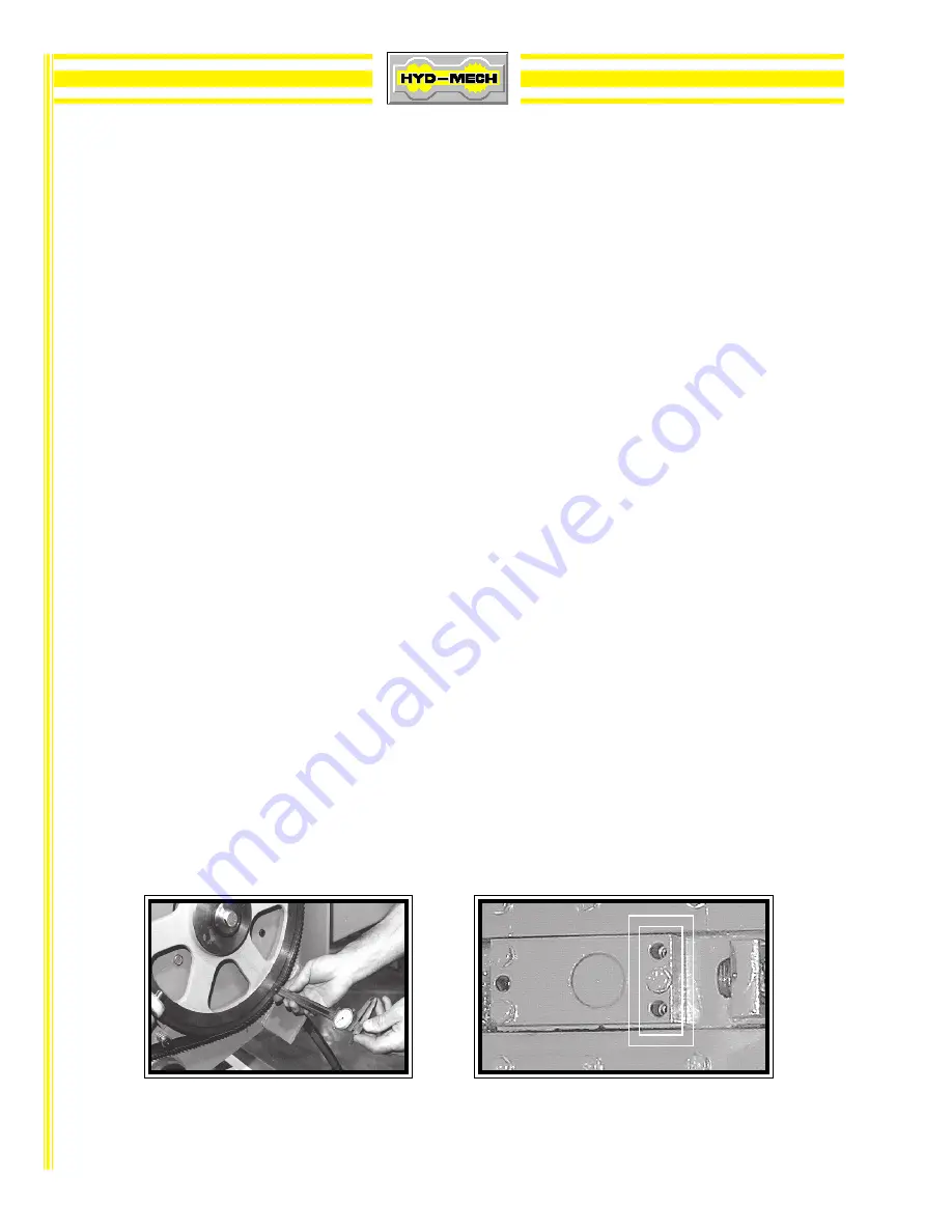
9A. . . . . As the blade tracking will stay fairly constant, it should be checked occasionally as shown on
the drive wheel tracking photo below. The blade teeth should protrude from .185" to .200" fromthe
face of the blade wheels. If the tracking requires adjustment, follow the instructions below.
BL
BL
BL
BL
BLADE TRA
ADE TRA
ADE TRA
ADE TRA
ADE TRACKING ADJUSTMENT
CKING ADJUSTMENT
CKING ADJUSTMENT
CKING ADJUSTMENT
CKING ADJUSTMENT
10. First, inspect the blade wheels for wear or damage and repair as required. Blade tracking
adjustment should always begin at the wheel where the tracking is farthest out of specification .
Using the instructions below, adjust the worst wheel, jog the blade and recheck both wheels.
Repeat this process until both wheels are within specification.
10A. Idler Wheel Adjustment. -- On the blade tensioner slide assembly, there are three 9/16" hex
head bolts. Loosen the two bolts at the left end by 1/4 turn. Loosen the single bolt at the right side
of the slide assembly by 1/2 turn. In the two holes above and below this bolt are two 3/16" allen
key set screws. Turn both set screws 1/4 turn and tighten the hex bolt at the right, then the two
bolts at the left. Turning the set screws clockwise will pull the blade on to the wheel, and turning
counter clockwise will push the blade off the wheel. Each 1/4 turn will move the blade
approximately .02". There is also a single set screw at the left end of the slider. Turning it clockwise
will push the blade off the wheel.
Chec
Chec
Chec
Chec
Checkkkkking the b
ing the b
ing the b
ing the b
ing the blade tr
lade tr
lade tr
lade tr
lade trac
ac
ac
ac
ackkkkking with a calliper
ing with a calliper
ing with a calliper
ing with a calliper
ing with a calliper..... Idler wheel tr
Idler wheel tr
Idler wheel tr
Idler wheel tr
Idler wheel trac
ac
ac
ac
ackkkkking set scr
ing set scr
ing set scr
ing set scr
ing set screeeeews & he
ws & he
ws & he
ws & he
ws & hex bolts
x bolts
x bolts
x bolts
x bolts
f
f
f
f
found on the slide assemb
ound on the slide assemb
ound on the slide assemb
ound on the slide assemb
ound on the slide assembly
ly
ly
ly
ly.....
Содержание S-20 Series II
Страница 27: ...PG 4 2 S22 ELECTRICAL SCHEMATIC DWG S22 7 00 1b Pg 1 of 1 ...
Страница 28: ...PG 4 3 S22 WIRING DIAGRAM S22 7 00 2b Pg 1 of 1 ...
Страница 57: ...PG 8 2 ...
Страница 58: ...PG 8 3 ...


