background image

The boiler must be installed in a fixed loca-
tion  and 

only  by   authorised  person

  in

compliance  with  all  instructions  contained
in this manual. Furthermore, the installation
must be in accordance with current Standard
AS 5601and other regulations as applicable.

Use the template supplied to position all holes.

6.2.1

INSTALLATION

–  These  boilers  can  be  installed  in  all  normal

domestic  environments  as  a  room  sealed
multi function boiler.

–  These  boilers  can  also  be  installed  in  par-

tially covered areas, as per AS5601, with a
maximum  ambient  temperature  of  60°C
and  a  minimum  ambient  temperature  of  -
5°C.  It  is  generally  advisable  to  install  the
boilers below weathered roofs, on the bal-
cony  or  in  a  protected  niche,  to  protect
them from exposure to weathering agents
(rain,  hail  and  snow). All  boilers  provide  a
standard antifreeze function.

6.2.1.1

Anti-freeze function

The  boilers  are  equipped  with  anti-freeze
function which activates the pumps and the
burner  when  the  temperature  of  the  water
contained  inside  the  appliance  drops  to
below value PAR 10. The anti-freeze function
is ensured, however, only if:
– the boiler  is correctly connected to the 

gas and electricity supply circuits;

– the boiler is constantly fed;
– the boiler ignition is not blocked;
– the essential components of the 

boiler are all in working order

In  these  conditions  the  boiler  is  protected
against frost down to an environmental tem-
perature of -5°C.

ATTENTION: 

In the case of installation in a place where
the  temperature  drops  below  0°C,  the
connection pipes must be protected. 

6.2.2

COMPLEMENTARY 

ACCESSORIES

For  to  fix  the  boiler  to  the  wall,  can  be  sup-
plied  on  r eques t  t he  f ixing  jig  code
8075427,  complete  with  instructions  for
assembly.

6.2.3

CONNECTING UP SYSTEM

To protect the heat system from damaging
corrosion,  incrustation  or  deposits,  before
installation  it  is  extremely  important  to
clean  the  system  using  suitable  products
such  as,  for  example,  FERNOX.  Complete
instructions are provided with the products
but,  for  further  information  please  contact
the Hunt Heating technical department.
For  long-term  protection  against  corrosion
and  deposits,  the  use  of  inhibitors  such  as
FERNOX is recommended after cleaning the

system.  It  is  important  to  check  the  con-
centration  of  t he  inhibit or  af t er  each
system modification and during maintenan-
ce  following  the  manufacturer’s  published
instructions. The safety valve drain must be
connected  to  a  collection  funnel  to  collect
any  discharge  during  interventions.  If  the
heating system is on a higher floor than the
boiler, install the on/off taps supplied in kit
op tional  on  t he  heating  sy s t em
flow/return pipes. 

WARNING:  Failure  to  clean  the  heat

s

ystem or add an adequate inhibitor inva-

l

idates the appliance’s warranty.

Gas  connections  must  be  made  in  accor-
dance  with  current  standards  and  regula-
tions.  When  dimensioning  gas  pipes  from
the  meter  to  the  module,  both  capacity
volume  (consumption)  in  m

3

/h  and  gas

density must be taken into account. 
The  sections  of  the  piping  making  up  the
system  must  be  such  as  to  guarantee  a
supply  of  gas  sufficient  to  cover  the  maxi-
mum  demand,  limiting  pressure  loss
between the gas meter and any apparatus
being used to not greater than:
– 1.0 mbar for family II gases (natural gas);
– 2.0  mbar  for  family  III  gases  (butane  or

propane).

An adhesive data plate is sticked inside the
front panel; it contains all the technical data
identifying the boiler and the type of gas for
which the boiler is arranged.

6.3.1

Filter on the gas pipe

The  gas  valve  is  supplied  ex  factory  with  an
inlet filter, which, however, is not adequate to
entrap all the impurities in the gas or in gas

main pipes. To prevent malfunctioning of the
valve, or in certain cases even to cut out the
safety  device  with  which  the  valve  is  equip-
ped, install an adequate filter on the gas pipe.

6.2.4

SYSTEM FILLING

Filling of the boiler and the system is done by
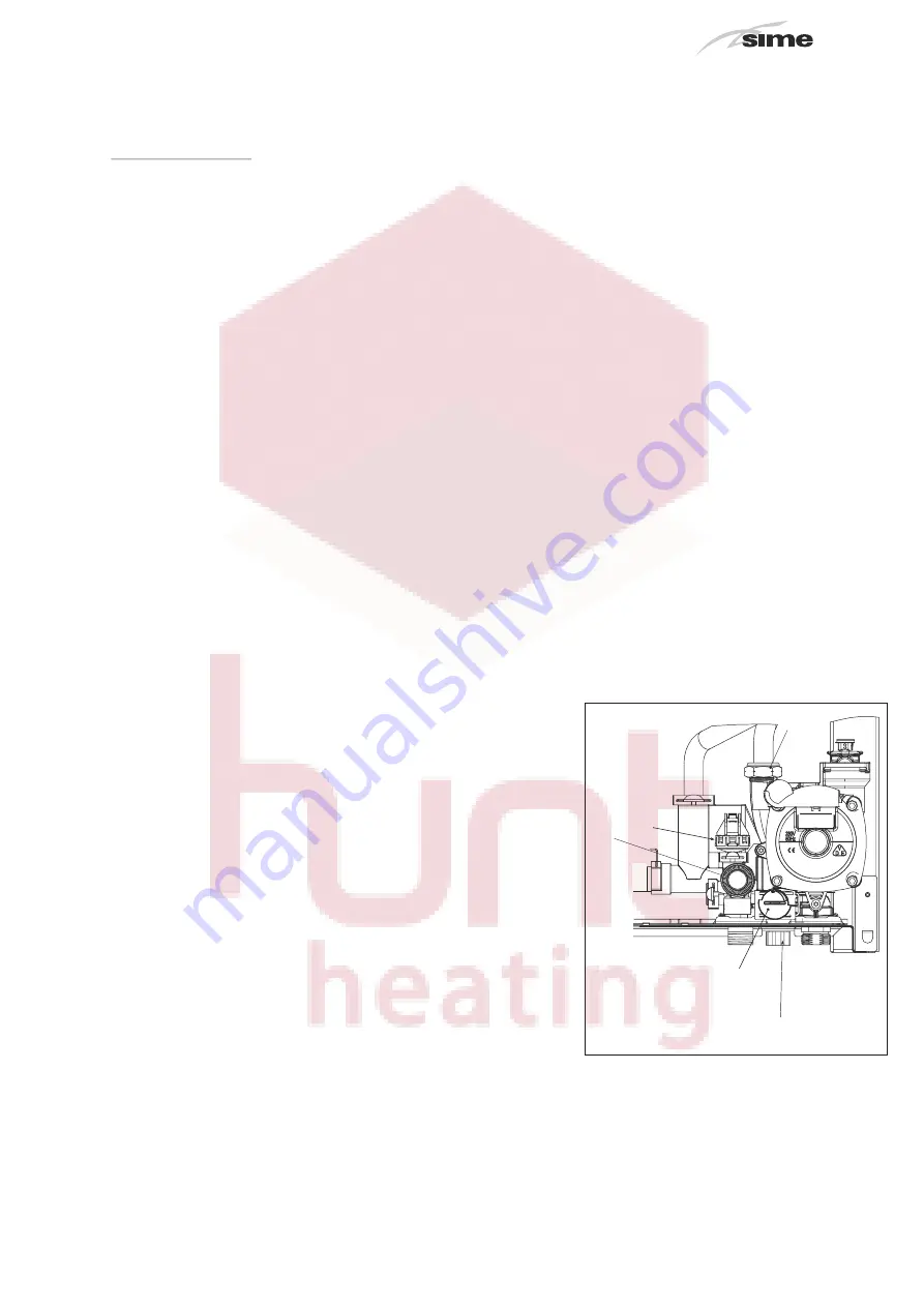
the system filling (3 fig. 4). 
The charge pressure, with the system cold,
must be between 

and

1.2 bar

Filling  must  be  done  slowly  so  as  to  allow
any air bubbles to be bled off through the air
valves. 
Should  the  pressure  have  risen  well  above
the limit expected, discharge the over pres-
sure by opening the pressure-relief valve.

6.2.4.1

Emptying the system

Use  the  drain  tap  to  empty  the  system  (5
fig. 4). Turn off the boiler before doing this.

6.2.5

FLUES/CHIMNEYS

A chimney or flue for the evacuation of the
combustion  products  into  the  atmosphere
must correspond to the requisites prescri-
bed by the laws in force.
In  particular,  the  specific  prescriptions  of
law  relative  to  boilers  with  forced  draught
(type C) must be respected.

6.2

INSTALLATION

Fig. 4

KEY

1
2 3 BAR safety valve

3 Boiler discharge

Automatic by-pass (blue)

4 Water pressure valve

5 Diverter valve

Page 17 of 34

1

4

5

2

3

MINIMUM CLEARANCES
for INTERNAL BOILERS
This Boiler must have the 
following clearances

Above - 200 mm
Below - 200 mm
Sides -    50 mm
Front -  600 mm 
min 50 mm to an openable panel

Содержание sime 30e

Страница 1: ...er Service and Installation Instructions 30i 30e WARNING The installation of this product must be carried out only by authorised personnel to the requirements of Australian Standard AS 5601 local auth...

Страница 2: ...ed instal ler the boiler is warranted by Hunt Heating against defects caused by the manufacturer s faulty materials and or work manship in respect to parts and labour for a period of twelve months com...

Страница 3: ...hat they do not play with the appliance LIGHTING AND OPERATION BOILER IGNITION fig 23 The first ignition of the boiler must be car ried out by qualified technical personnel Successively if it is neces...

Страница 4: ...ted The display will be as shown in fig 25 TO SWITCH OFF THE BOILER fig 26 In the case of a short absence touch more than two second the key of the controls The display will be as shown in figure boil...

Страница 5: ...ersonnel Call a qualified technical personnel Call a qualified technical personnel Call a qualified technical personnel AL 05 AL 06 fig 28 b Press the key of the controls to re start the boiler If the...

Страница 6: ...on unless safe to do so Check why it was turned OFF Do the other gas appliances work Does it work If NO go to Q4 4 Room Thermostat Is the display very dim or not showing at all Is the room thermostat...

Страница 7: ...s LPG Internal External Gas pressure Settings Max Pa Adjusted output setting kW Central Heating Water treatment System Volume Litres No Yes Yes Product Qty Used Litres Dilution rate Litres per 100 lit...

Страница 8: ...nel control 9 Boiler should start fan pump and ignite gas If it fails first few times this may be just residual air In the gas line A noisy water pump indicates there is air in the water pipes 10 Boil...

Страница 9: ...Where all the major items are their functions and how to check and turn them on or off Simple fault resolution i e power on 5 How to check and remove air in the radiators Give them a bleed key 6 The...

Страница 10: ...ct phone number Work Completed Service Service 3 4 year 5 year 7 Date Date Service technician Service technician Name PIC L icence No Name PIC L icence No Service Company Service Company Contact phone...

Страница 11: ...Service Service 7 8 year 11 year 13 Date Date Service technician Service technician Name PIC L icence No Name PIC L icence No Service Company Service Company Contact phone number Contact phone number...

Страница 12: ...6 0 INSTALLER INSTRUCTIONS CONTENTS 6 1 DESCRIPTION OF THE BOILER page 13 6 2 INSTALLATION page 18 6 3 CHARACTERISTICS page 26 6 4 USE AND MAINTENANCE 6 5 FAULT FINDING page 30 page 32 Page 12 of 34...

Страница 13: ...led boiler This manual gives the instructions for The instructions given in this manual are provided to ensure proper installation and operation of these boilers 6 1 DESCRIPTION OF THE BOILER CONNECTI...

Страница 14: ...kg NG mm dia LPG 0 85 mm dia 1 45 NG LPG2 50 kPa 0 79 kPa 13 injectosr 3 0 Bar 6 1 litres 85 C 10 litres 1 2 Bar Water content boiler Maximum water head Maximum temperature Capacity of the heating exp...

Страница 15: ...safety valve 9 Water pressure valve 10 By pass 11 Boiler discharge 12 Expansion vessel 13 Pressure Guage 14 Connection plate 15 Gas valve compulsory 16 C H flow valve recommended 17 C H return valve...

Страница 16: ...Y 1 Control panel 2 Circulation pump 3 Air relief valve 4 Burners 5 Expansion vessel 6 Air pressure switch 7 Fan 8 C H sensor 9 Primary exchanger 10 Ignition detection electrode 11 Gas valve FORMAT DG...

Страница 17: ...ns The safety valve drain must be connected to a collection funnel to collect any discharge during interventions If the heating system is on a higher floor than the boiler install the on off taps supp...

Страница 18: ...th a density of 50 kg m The maximum total length which is the sum of lengths of the aspiration and discharge pipes is determined by the loss of charge of the single accessories inser ted and must not...

Страница 19: ...ss of a DGT 30i boiler installation allowed as the sum of the head losses of the accessories used is less than 9 5 mm H2 O 93 2 Pa Intake Outlet 7 meter horizontal pipe 80 x 0 25 2 45 Pa 1 75 17 20 7...

Страница 20: ...4 8 39 2 47 1 from No 1 to 6 4 8 5 6 47 1 54 9 from No 1 to 7 5 6 6 5 54 9 63 7 from No 1 to 8 6 5 7 3 63 7 71 6 from No 1 to 9 7 3 7 8 71 6 76 5 from No 1 to 10 7 8 8 4 76 5 82 4 without diaphragm 8...

Страница 21: ...ventilation Space heaters up to 50 MJ h input 150 150 Other appliances up to 50 MJ h input 500 500 Appliances over 50 MJ h input and up to 150 MJ h input 1000 1000 n Appliances over 150 MJ h input 150...

Страница 22: ...e remote control of the boiler except release of the boiler When the connection has been made the boiler display will show the following messa ge Cr For installation and use of the remote con trol fol...

Страница 23: ...Fan EAR Ignition detection electrode EV1 2 Gas valve coil PF Smoke pressure switch M Modulator SM1 SM2 Heating sensor PA Water pressure switch TA ROOM THERMOSTAT SE External sensor S AUX Auxiliary sen...

Страница 24: ...e anomaly is signalled D H W SET Press the key to display the D H W temperature value set NON OPERATIONAL HEATING SET Press the key to display the heating temperature value set value not realtive to t...

Страница 25: ...1 18 Re ignition delay 0 10 Min 1 03 19 Modulation D H W flowmeter Disabled 01 1 Enabled 29 Anti legionella only D H W tank Disabled C 1 50 80 PARAMETERS RE SET PAR DESCRIPTION RANGE U UN NIIT T INC D...

Страница 26: ...r will not function for both services 6 3 6 ELECTRONIC IGNITION Ignition and flame detection is controlled by a single electrode on the burner which gua rantees reaction in the case of accidental exti...

Страница 27: ...as a function of rate of flow in the graph in fig 16 To obtain the maximum head available to the system turn off the by pass by turning the union to the vertical position fig 17 0 200 1600 1400 1200...

Страница 28: ...of the generator in the following way Turn the main switch off to stop electric power reaching the boiler and close the gas feed cock Remove the outer casing and the gas burner manifold unit To clean...

Страница 29: ...gas connections after assembly using soapy water or a product made specifically for the purpose being sure not to use open flame 6 4 2 1 New fuel configuration Access the parameters section by pres s...

Страница 30: ...22 a If the pressure detected by the water pressure valve is lower than 0 5 bar the boiler stops and the display shows the alarm AL 02 Bring the pressure back to normal by means by acting on the tele...

Страница 31: ...installer for PAR 1 and the self detection carried out by the card causes the activation of the alarm the boiler will not function and the display will show anomaly AL 12 Reset PAR 1 to de activate t...

Страница 32: ...Replace the fan Is there voltage available to the pump Replace clock the thermostat Check pump connection Is pump shaft free to rotate Replace the pump Make it free to rotate Has the PCB ignition lock...

Страница 33: ...BLANK PAGE Page 33 of 34...

Страница 34: ...30e CENTRAL HEATING BOILER version 1 Issued June 2010 HYDRONIC SYSTEMS Australia Pty Ltd 11 Fiveways Boulevard Keysborough Victoria 3173 Telephone 1300 00 1800 Facsimile 9798 5133 www huntheat com au...

Отзывы: