


1022410 – 0001 Rev. 2
5–10 Hardware installation
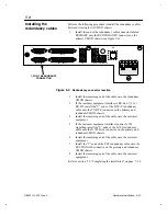
1.
Install a multidrop cable connector onto connector P2 on the
first UMOD chassis (chassis #1). Connect the other end of
the cable to connector P3 on chassis #2. See figure
5-7
for
connector locations.
TC
G.703 BAL
REDUNDANCY
ESC SIGNALS
TO DTE
SD
IDI
M&C
STATION CLK
DDO
RD
TD
RC GND
RD
A
B
C
D
E F012
3
4
5
67
89
A
B
C
D
E F012
3
4
5
67
89
A
B
C
D
E F012
3
4
5
67
89
A
B
C
D
E F012
3
4
5
67
89
MULTIDROP
CONNECTOR P2
MULTIDROP
CONNECTOR P3
P2
P3
S1
S2
S3
S4
TP1
TP2
TP3
TP4
TP5
Figure 5-7
Multidrop connectors location
Perform the following procedure to install the multidrop cables.
2.
Repeat step 1 to install multidrop cables between the
remaining UMOD chassis as shown in figure 5-6.
Refer to section 5.7, “Setting the chassis ID code” on page 5–11.