


1022410 – 0001 Rev. 2
Hardware installation 5–5
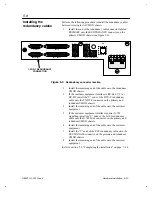
Upon startup, the light-emitting diode (LED) on the UMOD
front panel will begin cycling through a series of codes as
the UMOD initializes its internal components and performs
full-function diagnostics self-tests. (See figure 5-3 for LED
location.)
If the tests are successful, you will see the sequence of
displays on the LED readout as presented in table 5-1 . Each
is a solid display, not flashing. The presence of a dot
indicates that the UMOD board failed a test.
MODEM
U
N
I V
E
R
S
A
L
SLOT #2
SLOT #1
(OPTIONAL RFM BOARD)
Figure 5-3
UMOD front panel LEDs