MODEL 244/244OS TOOL
HUCK FASTENERS
12
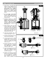
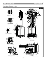
6. Hold handle in vise with bottom
facing up. Position Muffler (57) on
center of Cylinder Head (60),
Place Gasket (54) on Cylinder
Assembly (51), place Bottom
Plate (56) on top of Gasket and
secure with 3 Button Head
Screws (55) using 1/8 hex key.
(Fig. 6)
7. Turn tool upright. Drop Spring
(65) into Throttle valve hole in
cylinder. Push Throttle Valve (67)
with O-rings (66) in place into
cylinder. (Fig. 6)
8. Assemble Trigger (5), Cable
Assembly (2) and Trigger Pin (3)
together and slide cable into
Handle (1). Align hole in Trigger
and hole in handle ears and install
Roll Pin (4) with a hammer and
punch. (Fig. 6)
9. Slide Throttle Arm (68) onto ball
end of Throttle Cable. Swing arm
until other end fits over throttle
valve.Place Lever Guard (94) over
Throttle Arm and install Pivot
Screw (64) through Throttle Arm .
Tighten with 5/32 hex key.
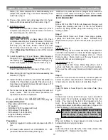
10. Install Swivel Assembly (86) in
Cylinder Assembly (51). (Fig. 9)
11. If Air Hose 115436 was removed,
reinstall in swivel assembly.
12. If Seat Assembly (80) is being
replaced push in seat and seal
assembly using soft drift taking
care not to damage ball seat
surface. (Fig. 9)
13. Assemble hydraulic Piston (18)
with new seals (16,17). Lubricate
with LUBRIPLATE or PARKER
SUPER-O-LUBE. (Fig. 9)
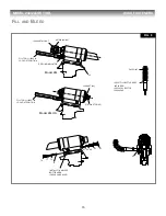
14. Install Nose Adapter (9) on front of
head. (Use VIBRA-TITE Huck
P/N 505125 on threads). Torque
to 50-60 ft. lbs. (Fig. 7)
15. Assemble Front Gland (12) Gland
Cap (11) O-ring (14) Back-up Ring
(13) and Polyseal (6). Thread
Piston Assembly Tool 123111-2
(244), 123111-8 (244OS) onto
5
4
3
2
1
64
63
62
61
60
59
58
57
56
55
54
53
52
51
50
41
40
39
33
29
25
C
C
A
A
SECTION A-A
66
65
66
67
68
94
Fig. 7a
Fig. 7b
SECTION SHOWING
POLYSEAL DIRECTION
123111-2
PISTON ASSEMBLY
TOOL
10
11
12
13 14
6
9
18
16
17 (2)
16 18
17 (2)
123111-8
PISTON ASSEMBLY
TOOL
9
11
12
13 14
6
244OS only
FIG. 6
FIG. 7


