MODEL 244/244OS TOOL
HUCK FASTENERS
22
Always check out the simplest possible cause of a
malfunction first. For example, an air hose not connected.
Then proceed logically, eliminating each possible cause
until the cause is located. Where possible, substitute
known good parts for suspected bad parts. Use
TROUBLESHOOTING CHART as an aid in locating and
correcting malfunction.
NOTE:
Piston Drift is when the air piston is in the down position,
but the hydraulic pull piston is not in the full forward
position. This causes an out of sequence condition.
1 Tool fails to operate when trigger is depressed.
a) Air line not connected
b) Throttle Valve O-rings (66), worn or damaged.
c)
Throttle valve Cable Assembly (2) is broken.
2 Tool does not complete fastener installation and
break pintail.
a) Air pressure too low
b) Air Piston Quad-Ring (52) worn or damaged.
c) Reservoir empty or low, refer to Fill and Bleed
section.
d) Air in hydraulic system, refer to Fill and Bleed
section.
e) Reservoir Springs (71) worn or damaged
f) Check for piston drift
3 Pintail stripped and/or swaged collar not ejected.
a) Check for broken or worn jaws in nose assembly,
refer to nose assembly data sheet.
b) Check for loose Retaining Nut (7)
c)
Check for piston drift.
4 Tool has piston drift.
a) Loose collet crashing into the front of the anvil,
this causes the relief valve to open allowing the
piston to drift. Tighten the collet and refer to Fill
and Bleed section.
b) Worn or damaged Return Pressure Relief Valve
in tool, inspect Seat Assembly (80), O-ring (27),
Back-up Rings (28), Steel Ball (81) and Valve
Spring (84). Replace if necessary.
c) Worn or damaged Piston Assembly (33); Inspect
O-ring (35), O-ring (38) and Back-up Rings (36).
Replace if necessary.
5 Hydraulic fluid exhausts with air or leaks at base
of handle.
a) Worn or damaged Gland Assembly (41); Inspect
Polyseal (43), O-rings (46 & 49) and Quad-Ring
(48). Replace if necessary.
6. Hydraulic fluid leaks at rear of Pull Piston (18)
a) Worn or damaged Rear Gland (19), inspect
Polyseal (24) and O-ring (20). Replace if
necessary.
7. Hydraulic fluid leaks at front of Pull Piston (18).
a) Worn or damaged Front Gland (12); Inspect
Polyseal (6), O-ring (14) and Back-up Ring (13).
Replace if necessary.
8. Pull Piston (18) will not return.
a) Throttle Valve (67) stuck; Lubricate O-rings (66).
b) Throttle Arm (68), Cable Assembly (2) or Trigger
(5) binding.
9. Air leaks at air Cylinder Head (60).
a). Worn or damaged O-ring (53). Replace if
necessary.
A
CCESSORIES
244 Tool
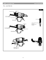
Fill and Bleed Bottle
(Fig.8)
-
120337
Seat Removal Tool
-
126136
Fill Tool Assy for reservoir
(Fig.8)
-
112465
Stall Nut
(Fig.8)
-
124090
Retaining Nut
(for
“Jiffy”
style noses)
-
125412
Piston Assembly Tool Kit
-
123110-11
Includes:
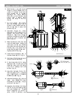
Piston Assembly Tool (Fig. 2)
-
123111-2
Spacer (Fig. 2)
-
123112-2
Service Tool Kit
-
120352-244
Includes:
Fill and Bleed Bottle (Fig.8)
-
120337
Fill Tool for reservoir (Fig.8)
-
112465
Stall Nut (Fig.8)
-
124090
244OS Tool
Fill and Bleed Bottle
(Fig.8)
-
120337
Seat Removal Tool
-
126136
Fill Tool Assy for reservoir
(Fig.8)
-
112465-1
Main Piston Assembly Tool Kit
-
123110-10
Includes:
Piston Assembly Tool (Fig. 2)
-
123111-8
Spacer (Fig. 2)
-
123112-8
Service Tool Kit
-
120352-244OS
Includes:
Fill and Bleed Bottle (Fig.8)
-
120337
Fill Tool Assy (Fig.8)
-
112465
T
ROUBLESHOOTING

