MODEL 244/244OS TOOL
HUCK FASTENERS
13
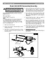
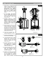
Piston (18). Slide complete Front Gland Assembly and
(Wiper Seal (10) 244 only) over Piston Assembly Tool
onto Piston. (Fig. 7)
16. Press entire piston and gland assembly into head.
Remove Piston Assembly Tool from piston. (Fig. 7)
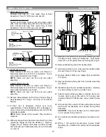
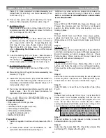
17. 244 Model: (Fig. 9)
Place Seals (20) and (24) on Rear Gland (19). Push
complete assembly into head and screw in End Cap
(21), and torque to 50 - 60 ft. lbs.
244OS Model: (Fig. 10)
Place seals (20 & 24) on Rear Gland (19). Push
complete assembly into head and screw in End Cap
(21), torque to 50 - 60 ft. lbs. Thread Stop (89) into
End Cap (21) two turns, thread Locknut (92) onto
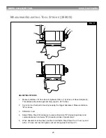
Piston Stop (89) and leave loose. For adjustment,
refer to
Measuring Tool Stroke
section of this manual
(Page 20).
18. Install Quad-Ring (72) and Spacer. Slide Reservoir
Plunger (73) in. {244OS Model: Install Spring (93) first,
then Spring (71); 244 Model: Install two Springs (71)}.
Screw Housing/Spacer Assembly into head. (Fig. 1)
19. 244 Model Only (Fig. 1 & 9)
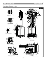
Push Pintail Deflector (22) onto rear of Piston (18).
20. Place O-ring (39) on Plug (40) and screw assembly into
Handle (1). (Fig. 6)
21. Install Pull (29) and Return (25) Gland Assemblies in
handle. Push head down on glands. Place tool in a vise
Head down and install 4 Screws (69) and torque to 170
inch pounds. (Fig. 6 & 9)
22. Tool is now completely assembled except for relief and
check valves. See fill and bleed procedure for
replacement of valve components.
F
ILL AND
B
LEED
244/244OS
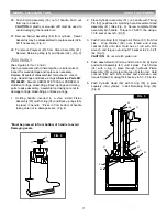
(Fig. 8)
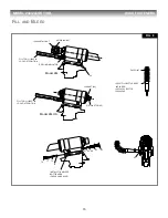
Equipment Required:
- Shop airline with 90-100 psi max.
- Air regulator
- Fill Bottle 120337 (supplied with tool).
- Fill Tool Assy 112465 (244)
- Fill Tool Assy 112465 (244OS)
- Large flat blade screwdriver
- Stall Nut 124090 (244)
Preparation:
1. Install air regulator in airline and set pressure to 20-40
psi.
2. Fill bleed bottle almost full of DEXRON III - ATF
(automatic transmission fluid) (See Fig. 8.)
Refill tool only when red line on plunger drops below the
red line on the reservoir housing or when tool is rebuilt.
REFILL: AUTOMATIC TRANSMISSION FLUID DEXRON
III, OR EQUIVALENT.
Step 1
Screw Fill Tool P/N 112465 into Reservoir Plunger, pull
Plunger into Housing and lock Fill Tool in full forward
position by tilting handle (long side touching tool) and
locking in place.
Step 2
Remove Relief Valve and Check Valve plugs, guides,
springs and balls from ports in head. Reinstall Plug
(85)and sleeve (83) in head in Relief Valve port (front of
tool).
Step 3
244 Model (Fig. 8)
Screw retaining nut onto Head Assembly. Screw Stall Nut
onto Piston and tighten to ensure full thread engagement.
Back off retaining nut until it engages stall nut. Check
Piston location.
Piston must be all the way forward and
locked with stall nut and retaining nut.
244OS Model (Fig. 8)
Loosen Locknut (92). Screw Piston Stop (89) in until it
pushes and holds the piston in the full forward position.
Piston must be all the way forward and locked in place with
Stop.
Step 4
Attach the tool air source momentarily to seat air piston at
bottom of cylinder - disconnect tool. With fill port facing up,
(check valve on side) lay tool on its side (See Fig. 8).
Step 5
Install fill bottle in head fill port (check Valve hole) (See
Fig. 8).
Step 6
Connect tool to shop air 20 to 40 psi. Cycle tool 20-30
times, watch for air bubbles escaping from the tool into
bottle. (You may rock the tool to free trapped air in the
tool.) Do not allow the air to re-enter the tool. When
cycling tool, always hold bottle up as shown in Figure 8 to
prevent drawing in air from empty part of bottle.
Step 7
When air bubbles no longer appear in bottle, remove fill
bottle while tool is lying on its side.
Step 8
Install the check valve Ball (75), Check Valve Guide (76)
and Spring (77). Replace the Plug (78).
WARNING: Air pressure MUST be set to 20 to
40 psi to prevent possible injury from high
pressure spray. If plug (78) is removed, fill
bottle must be in place before cycling tool.
!


