background image

MODEL 244/244OS TOOL

HUCK FASTENERS

6

S

AFETY

!

1

Safety Glossary

WARNINGS - Must be understood 
to avoid severe personal injury.

CAUTIONS

show conditions that 

will damage equipment and or 

structure.

Notes

- are reminders of required 

procedures.

Bold, Italic type and underlining -  

emphasizes a specific instruction.

2

Huck equipment must be maintained in a
safe working condition at all times and
inspected on a regular basis for damage
or wear.  Any repair should be done by a
qualified repairman trained on Huck
procedures. 

3

Repairman and Operator must read and
understand any Warning and Caution
stickers/labels supplied with equipment
before connecting equipment to any
primary power supply - - as applicable,
each of the sections in this manual have
specific safety, and other information.

4

When repairing or operating Huck
installation equipment always wear
approved eye protection.  Where
applicable, refer to ANSI Z87.1 - 1989

5

Disconnect primary power source
before doing maintenance on Huck
equipment.

6

If any equipment shows signs of
damage, wear or leakage, do not
connect it to the primary power supply.

7

Make sure proper power source is used
at all times.

8

Never remove any safety guards or
pintail deflector.

9

Never install a fastener in free air,
personal injury from fastener ejecting
may occur.

10

Do not abuse tool by dropping or using
it as a hammer.  Reasonable care of
installation tools by operators is an
important factor in maintaining tool
efficiency, eliminating downtime and in
preventing an accident which may
cause severe personal injury.

This instruction manual must be read with particular attention to the
following safety guidelines, by any person servicing or operating
this tool.  

MSDS and Safety Specifications are available on Hucks Tooling
Web-site www.hucktools.com. (Click on Safety Specifications)

Содержание 244 series

Страница 1: ...244OS PNEUDRAULIC INSTALLATION TOOL Huck International Inc 1998 Patent Pending HK 989 Rev 04 30 2002 HUCK FASTENERS HUCK FASTENERS HUCK FASTENERS HUCK FASTENERS HUCK FASTENERS HUCK FASTENERS HUCK FAS...

Страница 2: ...e August 1998 2 Huck Model 244 244OS Sound Power Level The sound level of the 244 244OS tool cycling without fastener is Sound Exposure Level SEL 74 3 dB A Peak Value 94 2 dB C The noise of the fasten...

Страница 3: ...PERATION 7 PREPARATION FOR USE 8 SERVICING THE TOOL GENERAL DAILY WEEKLY 8 DISASSEMBLY 9 11 ASSEMBLY 11 13 FILL AND BLEED 13 15 ASSEMBLY DRAWING PARTS LIST 244 16 17 ASSEMBLY DRAWING PARTS LIST 244OS...

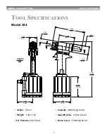
Страница 4: ...2 61 6 890 175 00 3 636 92 35 4 105 104 3 4 760 120 90 12 920 328 20 945 24 00 1 890 48 00 10 Stroke 562 in Weight 5 lbs 11oz Air Pressure 90 100 psi Capacity 4606 lbs 90 psi Speed Cycles 30 per minut...

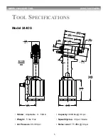
Страница 5: ...05 103 30 3 725 94 60 1 780 45 21 10 3 886 98 70 4 497 114 21 4 625 117 50 3 636 92 35 1 890 48 00 Stroke Adjustable 0 500 in Weight 5 lbs 11oz Air Pressure 90 100 psi Capacity 4606 lbs 90 psi Speed C...

Страница 6: ...g Huck installation equipment always wear approved eye protection Where applicable refer to ANSI Z87 1 1989 5 Disconnect primary power source before doing maintenance on Huck equipment 6 If any equipm...

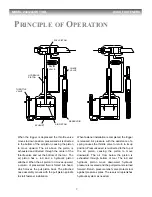
Страница 7: ...zed fluid is forced into head which moves the pull piston back The attached nose assembly moves with the pull piston spindle to start fastener installation When fastener installation is completed the...

Страница 8: ...SE GENERAL 1 The efficiency and life of any tool depends upon proper maintenance Regular inspection and correction of minor problems will keep tool operating efficiently and prevent downtime The tool...

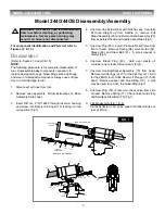
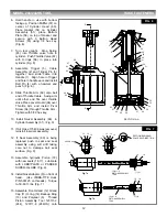
Страница 9: ...2 hex key Carefully lift Head straight up from Handle 1 remove Pull Gland Assembly 29 and Return Gland Assembly 25 from separated head and handle assemblies Fig1 5 Unscrew Plug 85 of return Pressure R...

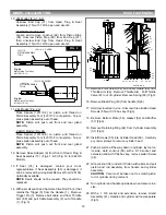
Страница 10: ...om Throttle Arm 68 and pull Cable Assembly 2 out of Handle 1 Fig 3 15 Remove Pivot Screw 64 and Lever Guard 94 from Throttle Arm 68 Remove Throttle Arm Pull Throttle Valve 67 out of cylinder Remove Sp...

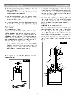
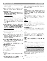
Страница 11: ...33 with O ring 35 and Back up rings 36 in place in handle Press in from bottom of handle taking care not to damage seals Fig 4 Must be pressed in from bottom of handle to avoid Damaging seals 2 Place...

Страница 12: ...w 64 through Throttle Arm Tighten with 5 32 hex key 10 Install Swivel Assembly 86 in Cylinder Assembly 51 Fig 9 11 If Air Hose 115436 was removed reinstall in swivel assembly 12 If Seat Assembly 80 is...

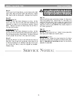
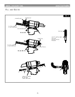
Страница 13: ...fill tool only when red line on plunger drops below the red line on the reservoir housing or when tool is rebuilt REFILL AUTOMATIC TRANSMISSION FLUID DEXRON III OR EQUIVALENT Step 1 Screw Fill Tool P...

Страница 14: ...servoir by placing a few drops of oil in hole and waiting for air bubbles to escape Push a pin or a scribe into hole to check for trapped air bubbles Replace plug Step 12 Unlock the fill tool and cycl...

Страница 15: ...BLEED BOTTLE HERE 85 Model 244OS LOCKNUT 92 PISTON STOP 89 Model 244 RED LINE INDICATOR 124090 STALL NUT RETAINING NUT 40 FILL TOOL 112465 IN LOCK OUT POSITION FILL TOOL 112465 1 IN LOCK OUT POSITION...

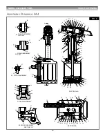
Страница 16: ...42 41 33 38 37 36 35 34 29 32 31 27 28 30 25 28 27 26 70 65 66 67 68 69 64 63 62 61 60 59 58 57 56 55 54 53 52 51 50 41 40 39 33 29 25 24 22 21 20 19 18 17 16 15 C C A A SECTION C C GLAND ASSEMBLY RET...

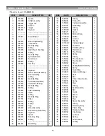
Страница 17: ...25557 Gland Assembly 1 42 126312 Gland O ring Assembly 1 43 506611 Polyseal 1 44 123904 Spacer 1 45 505939 Retaining Ring 1 46 500812 O Ring 1 47 48 501074 Quad Ring 1 49 500786 O Ring 1 50 505496 Tim...

Страница 18: ...2 1 64 63 51 50 40 39 33 29 25 24 70 71 72 73 39 40 74 75 15 13 14 12 11 9 16 17 18 19 21 B B SECTION A A SECTION B B 33 PISTON ASSEMBLY 41 GLAND ASSEMBLY 29 PULL GLAND ASSEMBLY 25 RETURN GLAND ASSEMB...

Страница 19: ...Retaining Ring 1 46 500812 O Ring 1 47 48 501074 Quad Ring 1 49 500786 O Ring 1 50 505496 Timing Pin 1 51 125560 Cylinder Assembly 1 52 501456 Quad Ring 1 53 500869 O Ring 1 54 125724 1 Gasket 1 55 5...

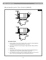
Страница 20: ...approximately equal to 247 inches 2 Cycle tool and hold piston back by keeping the trigger depressed Measure distance B as above 3 STROKE A B 4 Adjust Piston Stop 89 clockwise to reduce dimension B d...

Страница 21: ...nsert a 3 16 hexagonal T Wrench through Piston Stop 89 until it engages the internal hex in Hydraulic Piston 18 3 Thread the nose assembly onto the tool until it bottoms out Then back it off half to o...

Страница 22: ...inspect Seat Assembly 80 O ring 27 Back up Rings 28 Steel Ball 81 and Valve Spring 84 Replace if necessary c Worn or damaged Piston Assembly 33 Inspect O ring 35 O ring 38 and Back up Rings 36 Replace...

Страница 23: ...xture suspend 50 grams activated charcoal in 400 mL water and mix thoroughly Administer 5 mL kg or 350 mL for an average adult 5 FIRE FIGHTING MEASURES Flammable Properties Flash Point typical 370 F 1...

Страница 24: ...ire No Reactivity No Pressure No SARA TITLE III 313 This material is not known to contain any chemical s at a level of 1 0 or greater 0 1 for carcinogens on the list of Toxic Chemicals and subject to...

Страница 25: ...d above and Huck shall inspect products for which such claim is made Tooling Part s and Other Items not manufactured by Huck HUCK MAKES NO WARRANTY WITH RESPECT TO THE TOOLING PART S OR OTHER ITEMS MA...

Страница 26: ...30 8200 FAX 310 830 1436 Huck International Inc Industrial Fastener Division PO Box 8117 8001 Imperial Drive Waco TX 76714 8117 800 388 4825 254 776 2000 FAX 254 751 5259 Huck International Inc Instal...

Отзывы: