U-ONE
®
-SAFETY-LWL
Configuration manual
USL_KonfigManual-en_R3
23
4.5 Safe error switch
Required modules
USL(H) 42 Basic Device
UO-SCU Module
UO-SRC-R or UO-SGS-R module
Please see the specific module operating and assembly manuals for further
important information.
The error state can be assigned to a switching output (relay) using the configuration software.
The safe error switch must be used so that the application enters a safe state when the switch is
opened (see section 9).
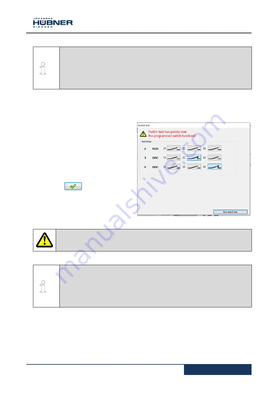
4.6 Switching test diagnostics
Pull-down menu analysis
Switching
test
The switching test can be used to change
the switching state using the US42Pro
configuration software. The switching test is
only available when the encoder shaft is
shut down.
The display area can be used to control
changes in the switching state.
Confirm with to activate the
switching test.
NOTE!
If the encoder shaft turns during the switching test, this will trigger an error.
The switching test takes priority over the programmed switch function.
4.7 PROFIBUS-DP interface and PROFIsafe profile (UO-SPB-1)
Required modules
USL(H) 42 Basic Device
UO-SCU Module
UO-SPB-1 module
Please see the separate configuration manual for further important information an
a full description of configuration.
The UO-SPB-1 module includes:
A PROFIBUS interface with PROFIsafe protocol, to transfer a safe position and speed
A fast process data channel via PROFIBUS, not safety-related
The “safe data” received via two
-channel data comparison is packaged in the PROFIsafe
protocol and is also transmitted to the controller via the PROFIBUS.
Fig. 4-9: Switching test


