Hardware options installation 106
WARNING:
To reduce the risk of personal injury, electric shock, or damage to the equipment,
remove the power cord to remove power from the server. The front panel Power On/Standby
button does not completely shut off system power. Portions of the power supply and some internal
circuitry remain active until AC power is removed.
WARNING:
To reduce the risk of personal injury from hot surfaces, allow the drives and the
internal system components to cool before touching them.
1.
Do one of the following:
o
For tower models, open and remove the bezel ("
Remove the tower bezel
" on page
21
).
o
For rack models, if installed, remove the security bezel (on page
21
).
2.
Power down the server (on page
20
).
3.
Remove all power:
a.
Disconnect each power cord from the power source.
b.
Disconnect each power cord from the server.
4.
Do one of the following:
o
For tower models, place the server on a flat, level surface with the access panel facing up.
o
For rack models, extend the server from the rack (on page
24
).
5.
Remove the access panel (on page
23
).
6.
Remove the air baffle (on page
25
).
7.
If installed, remove the PCI card from slot 9 ("
System board components
" on page
11
).
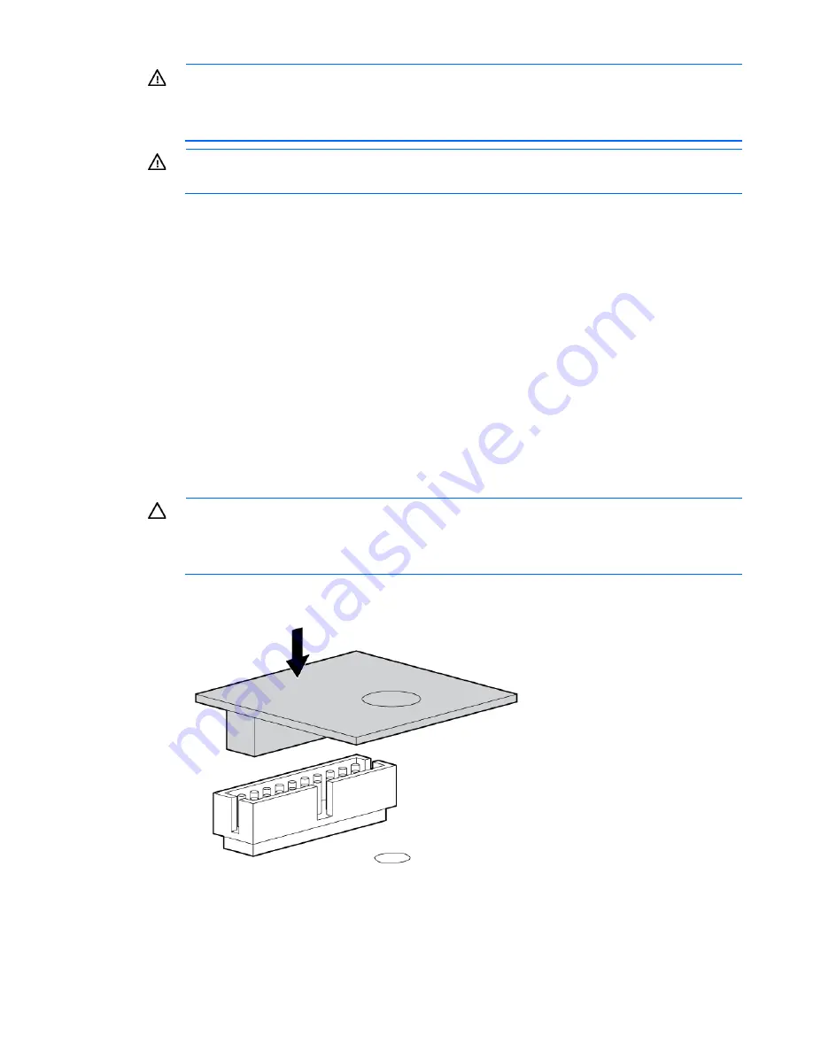
CAUTION:
Any attempt to remove an installed TPM from the system board breaks or disfigures
the TPM security rivet. Upon locating a broken or disfigured rivet on an installed TPM,
administrators should consider the system compromised and take appropriate measures to ensure
the integrity of the system data.
8.
Install the TPM board. Press down on the connector to seat the board ("
System board components
" on
page
11
).
Содержание ProLiant ML350p Gen8
Страница 19: ...Component identification 19 Item Connector Description 5 J8 Graphic card power connector ...
Страница 30: ...Operations 30 ...
Страница 39: ...Setup 39 12 Remove the air baffle 13 Remove the fan cage ...
Страница 46: ...Hardware options installation 46 o Cable routing to box 1 o Cable routing to box 2 ...
Страница 67: ...Hardware options installation 67 6 Remove the blank from box 3 7 Install the optical drive cage ...
Страница 99: ...Hardware options installation 99 i Connect the short mini SAS cables ii Connect the long mini SAS cables ...
Страница 137: ...Support and other resources 137 ...
Страница 138: ...Support and other resources 138 ...


