Hardware options installation 35
c.
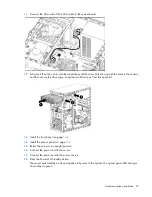
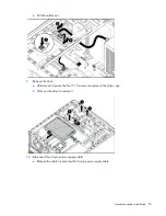
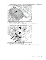
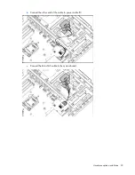
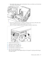
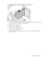
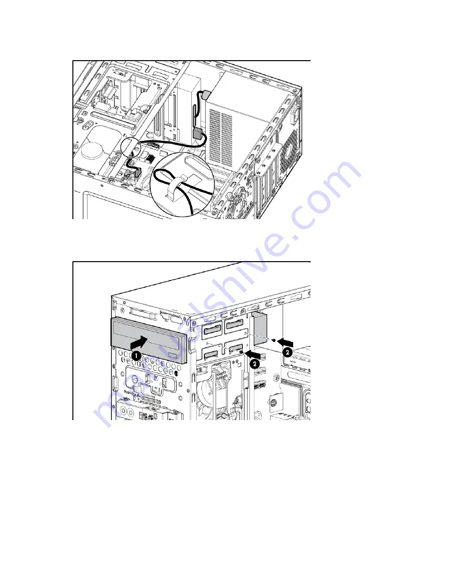
Pass the SATA cable through a cable clip at the bottom of the server, and then connect the other end
of the cable to the system board.
d.
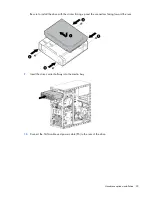
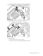
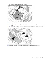
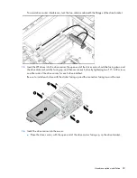
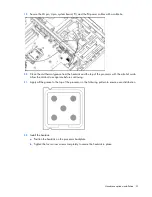
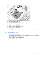
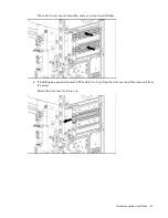
Fully insert the optical drive into the media bay until the screw holes line up with the holes in the
chassis, and then secure the drive cage using the two T-15 screws.
Use the T-15 screws available on the front I/O module for securing the optical drive.
10.
Install the front bezel (on page
14
).
11.
Install the access panel (on page
14
).
12.
Return the server to an upright position.
13.
Connect the power cord to the server.
14.
Connect the power cord to the power source.
15.
Press the Power On/Standby button.
The server exits standby mode and applies full power to the system. The system power LED changes
from amber to green.
Содержание ProLiant ML10
Страница 5: ...Contents 5 Documentation feedback 73 Index 74 ...
Страница 11: ...Component identification 11 Fan locations Item Description 1 Rear system fan 2 Processor heatsink fan assembly ...
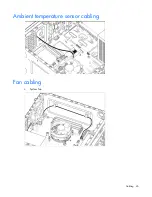
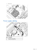
Страница 45: ...Cabling 45 Ambient temperature sensor cabling Fan cabling System fan ...
Страница 68: ...Support and other resources 68 ...
Страница 69: ...Support and other resources 69 ...

