2.
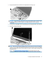
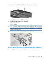
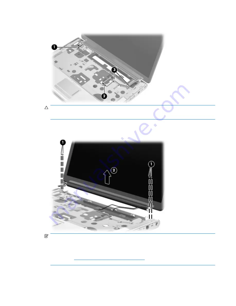
Remove the WLAN antenna cables from the clips
(3)
built into the top cover.
CAUTION:
Support the display assembly when removing the following screws. Failure to support
the display assembly can result in damage to the display assembly and other computer
components.
3.
Remove the four Phillips PM2.5×7.0 screws
(1)
that secure the display assembly to the computer.
4.
Remove the display assembly
(2)
.
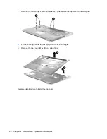
NOTE:
Steps 5 through 22 provide display assembly internal component removal information for
computer models equipped with AntiGlare display assemblies. See steps 23 through 32 for display
assembly internal component removal information for computer models equipped with BrightView
display assemblies.
NOTE:
See
Webcam/microphone module on page 53
for webcam/microphone module
replacement instructions for computer models equipped with BrightView display assemblies.
Component replacement procedures
77
Содержание Dv5-1010us - Pavilion - Core 2 Duo GHz
Страница 1: ...HP Pavilion dv5 Entertainment PC Maintenance and Service Guide ...
Страница 4: ...iv Safety warning notice ...
Страница 159: ...Universal Serial Bus Pin Signal 1 5 VDC 2 Data 3 Data 4 Ground Universal Serial Bus 151 ...
Страница 173: ......


