10.
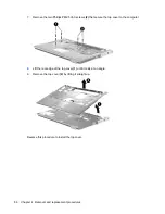
Release the zero insertion force (ZIF) connector
(1)
to which the keyboard cable is connected and
disconnect the cable
(2)
from the system board.
11.
Remove the keyboard.
12.
Disconnect the power button board cable
(1)
from the low insertion force (LIF) connector on the
system board.
13.
Disconnect the LED board cable
(2)
from the LIF connector on the system board.
14.
Remove the switch cover.
Reverse this procedure to install the switch cover and keyboard.
72
Chapter 4 Removal and replacement procedures
Содержание Dv5-1010us - Pavilion - Core 2 Duo GHz
Страница 1: ...HP Pavilion dv5 Entertainment PC Maintenance and Service Guide ...
Страница 4: ...iv Safety warning notice ...
Страница 159: ...Universal Serial Bus Pin Signal 1 5 VDC 2 Data 3 Data 4 Ground Universal Serial Bus 151 ...
Страница 173: ......


