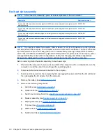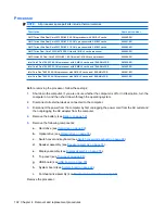
g.
USB board (see
USB board on page 90
).
h.
System board (see
System board on page 92
).
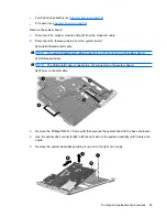
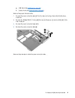
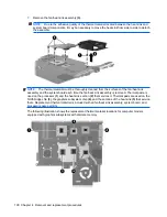
Remove the power connector cable:
1.
Remove the power connector cable
(1)
from the clips and routing channel built into the base
enclosure.
2.
Remove the Phillips PM2.5×7.0 screw
(2)
that secures the power connector and bracket to the
base enclosure.
3.
Remove the power connector bracket
(3)
.
4.
Remove the power connector cable
(4)
.
Reverse this procedure to install the power connector cable.
Component replacement procedures
97
Содержание Dv5-1010us - Pavilion - Core 2 Duo GHz
Страница 1: ...HP Pavilion dv5 Entertainment PC Maintenance and Service Guide ...
Страница 4: ...iv Safety warning notice ...
Страница 159: ...Universal Serial Bus Pin Signal 1 5 VDC 2 Data 3 Data 4 Ground Universal Serial Bus 151 ...
Страница 173: ......


