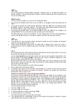
LEDs
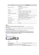
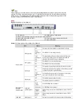
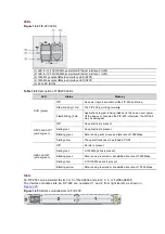
Figure 1-18
FIP-100 LEDs
(1) LED for 10/100/1000 Mbps electrical Ethernet interface 0
(2) LED for 10/100/1000 Mbps electrical Ethernet interface 1
(3) 1000 Mbps optical Ethernet interface LED (SFP0)
(4) 1000 Mbps optical Ethernet interface LED (SFP1)
(5) Run LED (RUN)
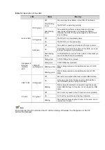
Table 1-18
Description of FIP-100 LEDs
LED
Status
Meaning
RUN (green)
Off
No power input is available or the FIP-100 has failed.
Slow blinking (1 Hz)
The FIP100 is working normally.
Fast blinking (8 Hz)
Application software is being loaded (in this case, never power
off the device or hot-swap the FIP100; otherwise the FIP100
may be damaged) or FIP-100 is not working.
SFP0 to SFP1
(yellow/green)
Off
No optical link is present.
Solid green
An optical link is present.
Blinking green
Data is being sent or received at a rate of 1000 Mbps.
Solid yellow
The optical transceiver failed to be detected.
GE0 to GE1
(yellow/green)
Off
No link is present.
Solid green
A 1000 Mbps link is present.
Blinking green
Data is being received or transmitted at a rate of 1000 Mbps.
Solid yellow
A 10/100 Mbps link is present.
Blinking yellow
Data is being received or transmitted at a rate of 10/100 Mbps.
Slots
An FIP-100 can be inserted in slot 2 or 3 of the A6604 and slot 2, 3, 4, or 5 of the A6608. FIP-
100 provides four MIM slots for some HP legacy MIMs. The MIM slots on FIP-100 are
numbered 1 to 4 from the bottom up and from right to left, as shown in
Figure 1-19
.

