background image

Chapter 6

Removing and Replacing Components

Removing and Replacing Core I/O Cards

248

Step 3.

 Disconnect any internal and external SCSI cables connected to the SCSI core I/O card.

Step 4.

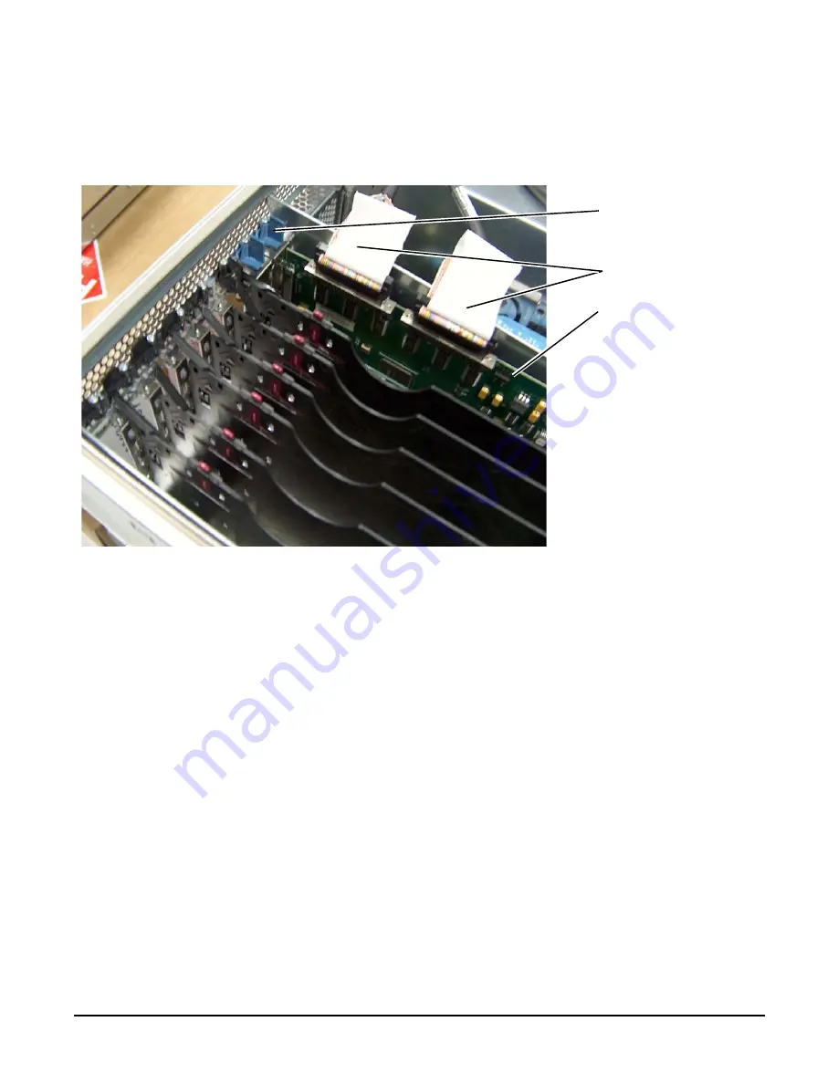
 Open the blue PCI card latch for slot 1 by twisting it clockwise.

Figure 6-45 SCSI I/O Card latch Location

Step 5.

Remove the internal and external SCSI cables from the SCSI core I/O card.

Step 6.

Remove THE SCSI core I/O card.

Installing the SCSI Core I/O Card

To install the SCSI core I/O card, follow these steps:

Step 1.

Insert the replacement SCSI core I/O card into slot 1.

SCSI PCI I/O Card Latch

For slot 1 (Closed)

SCSI Cables


SCSI Card


Содержание 9000 rp4410

Страница 1: ...User Service Guide HP 9000 rp4410 and HP 9000 rp4440 Manufacturing Part Number A9950 96011 ed4 Forth Edition Se tember 2008 Copyright 2003 2008 Hewlett Packard Development Company L P ...

Страница 2: ...nts accompanying such products and services Nothing herein should be construed as constituting an additional warranty HP shall not be liable for technical or editorial errors or omissions contained herein Printed in U S A Intel Pentium Intel Inside Itanium and the Intel Inside logo are trademarks or registered trademarks of Intel Corporation or its subsidiaries in the United States and other count...

Страница 3: ...SCSI Port Ultra 3 68 Pin 36 Additional Controls and LEDs 39 Powering the Server On and Off 42 Power States 42 Powering On the Server 43 Powering Off the Server 44 2 System Specifications System Configuration 45 Dimensions and Values 46 Grounding 46 Electrical Specifications 47 AC Power Cords 47 Circuit Breaker 47 System Power Specifications 47 Power and Cooling 49 Environmental Specifications 50 O...

Страница 4: ...dditional Components 63 Service Tools Required 63 Accessing a Rack Mounted Server 64 Accessing a Pedestal Mounted Server 65 Front Panel Controls and Indicators 66 Additional Controls and Indicators 70 Front Bezel 71 Front and Top Covers 72 Hot Swappable Chassis Fan Units 75 I O Baseboard Assembly 77 System Battery 81 Installing Power Supplies and Disk Drives 83 Installing Processors 86 Installing ...

Страница 5: ...ying the Server Configuration Using Boot Console Handler 135 Troubleshooting 136 Troubleshooting Methodology 136 Troubleshooting Using the Server Power Button 136 Server Does Not Power On 137 BCH Menu is Not Available 138 Operating System Does Not Boot 138 Operating System Boots with Problems 138 Intermittent Server Problems 138 DVD Problems 139 Hard Drive Problems 139 Console Problems 139 Downloa...

Страница 6: ...k and I O Path Logging 169 Core I O Connections 171 System I O Board Switches and Jumpers 172 6 Removing and Replacing Components Safety Information 176 Required Service Tools 176 Accessing a Rack Mounted Server 177 Extend the Server from the Rack 177 Inserting the Server Into the Rack 178 Accessing a Pedestal Mounted Server 178 Front Bezel 180 Removing the Front Bezel 180 Replacing the Front Beze...

Страница 7: ...R 225 Removing a PCI PCI X Card Offline 226 Installing a PCI Card Offline 227 OLX Dividers 228 Removing an OLX Divider 228 Replacing an OLX Divider 231 U320 SCSI Enablement and Conversion Procedures 231 Time Required 231 Upgrade Tasks 232 Back Up Your System 232 Removing Server Components 232 Removing the SCSI Duplex Board 233 Removing the SCSI Backplane 235 Replacing the SCSI Backplane 237 Instal...

Страница 8: ...moving the Power Distribution Board 261 Replacing the Power Distribution Board 262 DVD Drive 263 Removing a DVD Drive 263 Replacing a DVD Drive 264 DVD I O Board 265 Removing a DVD I O Board 265 Replacing a DVD I O Board 266 Display Board 267 Removing the Display Board 267 Replacing the Display Board 269 QuickFind Diagnostic Board 269 Removing the QuickFind Diagnostic Board 269 Replacing the Quick...

Страница 9: ... Dimensions and Values 46 Table 2 3 Power Cords 47 Table 2 4 System Power Specifications 48 Table 2 5 System Power Requirements 49 Table 2 6 Typical Configuration Power Values 49 Table 2 7 Physical and Environmental Specifications 53 Table 3 1 Server Dimensions and Values 60 Table 3 2 Installation Sequence Checklist 61 Table 3 3 Control Panel LED Definitions 68 Table 3 4 Switch and Button LED Defi...

Страница 10: ...Board LED States 167 Table 5 7 16 DIMM Memory Extender Board LED States 168 Table 5 8 Internal Disk and DVD Paths 169 Table 5 9 Extended Core I O Paths 169 Table 5 10 PCI I O Paths 169 Table 5 11 System I O Board Indicators Connectors and Jumpers 173 Table 6 1 DIMM Filler Requirements for 16 DIMM Memory Extender Board 189 Table 6 2 DIMM Filler Requirements for 32 DIMM Memory Extender Board 190 Tab...

Страница 11: ...Figure 1 22 I O Baseboard LEDs Buttons and Sensors 41 Figure 2 1 Airflow Through HP 9000 rp4410 and rp4440 Servers 52 Figure 3 1 HP 9000 rp4410 and rp4440 Servers Top View 56 Figure 3 2 HP 9000 rp4410 and rp4440 Servers with Bezel Removed Front View 57 Figure 3 3 HP 9000 rp4410 and rp4440 Servers Rear View 57 Figure 3 4 Accessing T 25 Screws 65 Figure 3 5 Pedestal Mounted Server 66 Figure 3 6 Fron...

Страница 12: ...igure 3 39 Installing SCSI Cable B to the SCSI Adapter Board 114 Figure 3 40 Ports on Server Rear 117 Figure 3 41 iLO MP Setup Flowchart 120 Figure 3 42 Web Login Page 128 Figure 3 43 Status Summary Page 129 Figure 3 44 Front Control Panel LEDs 140 Figure 3 45 QuickFind Diagnostic Panel 143 Figure 5 1 PCI PCI X LEDs 160 Figure 5 2 Front Control Panel LEDs 162 Figure 5 3 QuickFind Diagnostic Panel ...

Страница 13: ... 230 Figure 6 33 SCSI Cable B Connection to the SCSI Backplane 234 Figure 6 34 Remove the SCSI Duplex Board 235 Figure 6 35 Remove the SCSI Backplane Jumper Cable 236 Figure 6 36 Lift the SCSI Backplane Out of the Chassis 237 Figure 6 37 Aligning the Bracket Tabs on the SCSI Duplex Board 238 Figure 6 38 Connecting SCSI Cable B to the SCSI Adapter Board 239 Figure 6 39 Unplugging SCSI Cable B from ...

Страница 14: ...Figures 14 Figure 6 56 Display Board Removal and Replacement 268 Figure 6 57 QuickFind Diagnostic Board Removal and Replacement 270 ...

Страница 15: ...chnical product and support information for authorized service providers system administrators and HP support personnel This document is not a tutorial New and Changed Information in This Edition This following changes are included in this edition The User Service Guide includes the contents of the Maintenance Guide and the Operations Guide Server specification and installation information I O bas...

Страница 16: ...Appendix B Utilities Provides information on the utilities on the server such as Boot Console Handler BCH and Integrity iLO MP Appendix C Physical and Environmental Specifications Provides temperature and airflow information for minimum typical and maximum configurations for the server It also lists the server and rack weights and dimensions Typographic Conventions This document uses the following...

Страница 17: ...you type Command A command name or qualified command phrase Option An available option Screen Output Example of computer screen output The contents are optional in formats and command descriptions If the contents are a list separated by you must select one of the items The contents are required in formats and command descriptions If the contents are a list separated by you must select one of the i...

Страница 18: ...lished by Prentice Hall The http www hp com hpbooks website lists the HP books that Prentice Hall currently publishes including the following HP UX 11i System Administration Handbook http www hp com hpbooks prentice ptr_0130600814 html HP UX Virtual Partitions http www hp com hpbooks prentice ptr_0130352128 html HP Books are available worldwide through bookstores online booksellers and office and ...

Страница 19: ... physical identification of problem hardware and the QuickFind diagnostic LED panel speeds problem diagnosis by identifying defective or mismatched hardware components HP 9000 rp4410 Server The HP 9000 rp4410 server is a PA 8900 based server in a 4U form factor It is based on the same hardware as the HP 9000 rp4440 server but in the rp4410 server two of the four processor sockets are disabled usin...

Страница 20: ...4410 and rp4440 Server Views 20 HP 9000 rp4410 and rp4440 Server Views Figure 1 1 Figure 1 2 and Figure 1 3 show the top front and rear views of the HP 9000 rp4410 and rp4440 servers Figure 1 1 HP 9000 rp4410 rp4440 Server Top View ...

Страница 21: ... subsystems within the HP 9000 rp4410 and rp4440 servers I O Subsystem The following is supported on the HP 9000 rp4410 and rp4440 servers PCI X slots available 8 Two dedicated PCI slots Slot 1 is for SCSI slot 2 is for LAN Four hot pluggable PCI X 66 MHz 64 bit 3 3V 25W slots with shared busses and I O Slots 3 and 4 share capabilities and slots 5 and 6 share capabilities Two hot pluggable PCI X 1...

Страница 22: ...I U320 or U160 68 pin connectors U160 for PA8800 only One or two 10 100 1000Base T ethernet LAN connectors for copper cable Two USB 2 0 ports Three DB 9 ports console UPS and modem Optional dual channel U320 RAID controller two 68 pin external connectors replaces SCSI interface Processors The following is supported on the HP 9000 rp4410 and rp4440 servers 800 MHz 1 5 GB cache or 1 GHz 1 5 GB cache...

Страница 23: ...ovides the controls and indicators commonly used for operation DVD RW drive with CD write capability IDE interface 48x speed Optional slimline DVD drive Power button and LED indicators for system status LED based diagnostic panel Mass Storage The following is supported on the HP 9000 rp4410 and rp4440 servers Up to two SCSI hot pluggable hard disk drives Integrated Ultra 3 SCSI dual channel contro...

Страница 24: ...ents The server firmware generates event IDs similar to chassis codes for errors events and forward progress to the Integrity Integrated Light Out Management Processor iLO MP through common shared memory The Integrity iLO MP interprets and stores event IDs Reviewing these events helps you diagnose and troubleshoot problems with the server Dimensions and Values Table 1 1 lists the dimensions and th...

Страница 25: ...4 shows the control panel on the server front Figure 1 4 Control Panel Front View of Server with Bezel Figure 1 5 shows how to access the control panel The front control panel access door is on the bezel Figure 1 5 Accessing the Control Panel Control Panel ...

Страница 26: ...ED Fault Flashing at 2 Hz Red Hard fault system halted System LED Off Off N A System off Power LED On Steady Green Power normal Power LED On Flashing at 1 Hz Yellow Housekeeping voltage present Power LED Off Off Off Power off Disk LED Flashing at rate of disk activity Green Disk activity Thermal LED OK Steady Green Thermal OK Thermal LED Warning Flashing at 1 Hz Yellow Thermal warning Locator Butt...

Страница 27: ...stem is at BCH pressing the power button does the following From zero to five sceonds has no effect More than five seconds then released causes an immediate hard power off If power is on but the OS has been shut down pressing the power button Momentarily less than one second has no effect More than one second but less than five seconds do not use This initiates e buzzer functions that are not supp...

Страница 28: ...the server signal the operational status of the following components Power supplies iLO MP LAN Gigabit Ethernet card LAN PCI slots 3 8 Figure 1 7 shows the rear panel LEDs Figure 1 7 Rear Panel LEDs Power Supply Status LEDs Each power supply unit has three status LEDs located on the power supply rear side The front control panel power status LED reports a consolidated status of all power supplies ...

Страница 29: ...er Fail LED Amber Status Off Off Off No ac power is applied to all PSUs Off Off On No ac power is applied to this PSU only Blinking Off Off ac present and the standby outputs are on On Off Off PSU dc outputs are on and OK Off Off On Power supply failure On Blinking Off Predictive failure The PSU is about to fail because of a poorly performing fan On Off Blinking Current limit on 48 VDC output Pred...

Страница 30: ...LAN uses an RJ 45 type connector This connector has two LEDs LAN link and LAN activity that signal status and activity Figure 1 9 iLO MP LAN LEDs Table 1 5 provides iLO MP LED status descriptions Table 1 5 iLO MP LED Status Descriptions LED Condition Status 100 M amber On Linked at 100 MBs No activity 100 M amber Blinking Linked at 100 MBs Activity present 10 M green On Linked at 10 MBs No activit...

Страница 31: ...or This connector has four LEDs three LAN link and one LAN activity that signal link speed and activity Figure 1 11 Single Port GigE LAN Connector and LEDs Table 1 6 iLO MP LED Status Descriptions LED Condition Status 100 M green On Linked at 100 MBs No activity 100 M green Blinking Linked at 100 MBs Activity present 10 M amber On Linked at 10 MBs No activity 10 M amber Blinking Linked at 10 MBs A...

Страница 32: ... 7 Single Port GigE LAN LED Status Descriptions LED Color Condition Status Activity Green On Linked No activity Activity Green Off No link Activity Green Blinking Linked Activity present 1000 BaseT Green On Link speed 1000 MBs 100 BaseT Green On Link speed 100 MBs 10 BaseT Green On Link speed 10 MBs Speed LEDs Off 10 Mbit s Port A RJ 45 Connectors Port B Green 100 Mbit s Activity Link LEDs Flashin...

Страница 33: ...it Ethernet card in slot 2 are factory installed Table 1 8 Dual Port GigE LAN Card LED Status Descriptions LED Condition Status Activity Flashing Linked data traffic Activity Solid Active link Speed Off Link speed 10 Mbit s Speed Green Link speed 100 Mbit s Speed Amber Link speed 1000 Mbit s Gigabit Ethernet LAN Port 3 Serial Ports Aux iLO MP LAN Port USB Ports Video Port Disabled HBA Ultra 3 SCSI...

Страница 34: ...r VGA Port The VGA video port is disabled on the rp4410 and rp4440 servers Serial Ports Figure 1 15 and Table 1 10 show the serial port connector and pinouts Figure 1 15 Serial Port Connector Table 1 9 USB Pinouts Pin Number Signal Description 1 5 VDC 2 MR 3 PR 4 Ground Table 1 10 Serial Port Pinouts Pin Number Signal Description 1 Data carrier detect ...

Страница 35: ...ransmit data 4 Data term ready 5 Ground 6 Data set ready 7 Request to send 8 Clear to send 9 Ring indicator Table 1 11 iLO MP LAN Port Pinouts Pin Number Signal Description 1 TXP 2 TXN 3 RXP 4 Not used 5 Not used 6 RXN 7 Not used 8 Not used Table 1 10 Serial Port Pinouts Continued Pin Number Signal Description 1 8 100M Link Activity Green LED 10M Link Activity Amber LED ...

Страница 36: ...7 Gigabit Ethernet LAN Port SCSI Port Ultra 3 68 Pin Two Ultra 3 68 pin SCSI connectors are located on the HBA located in PCI slot 1 The upper connector supports SCSI channel A and the lower connector supports SCSI channel B Table 1 12 Gigabit Ethernet LAN Port Pinouts Pin Number Signal Description 1 RXP 2 RXN 3 TXP 4 Not used 5 Not used 6 TXN 7 Not used 8 Not used ...

Страница 37: ...35 DB 12 2 S2 DB 13 36 S36 DB 13 3 S3 DB 14 37 S37 DB 14 4 S4 DB 15 38 S38 DB 15 5 S5 DB P 1 39 S39 DB P 1 6 S6 DB 0 40 S40 DB 0 7 S7 DB 1 41 S41 DB 1 8 S8 DB 2 42 S42 DB 2 9 S9 DB 3 43 S43 DB 3 10 S10 DB 4 44 S44 DB 4 11 S11 DB5 45 S45 DB 5 12 S12 DB 6 46 S46 DB 6 13 S13 DB 7 47 S47 DB 7 14 S14 DB P 48 S48 DB P 15 S15 49 S49 16 S16 DIFFSENS 50 S50 17 S17 TERMPWR 51 S51 TERMPWR 18 S18 TERMPWR 52 S...

Страница 38: ...5 S25 RST 59 S59 RST 26 S26 MSG 60 S60 MSG 27 S27 SEL 61 S61 SEL 28 S28 C D 62 S62 C D 29 S29 REQ 63 S63 REQ 30 S30 I O 64 S64 I O 31 S31 DB 8 65 S65 DB 8 32 S32 DB 9 66 S66 DB 9 33 S33 DB 10 67 S67 DB 10 34 S34 DB 11 68 S68 DB 11 Table 1 13 SCSI Port Pinouts Continued Pin Number Signal Description Pin Number Signal Description ...

Страница 39: ...d with one DVD drive DVD R and DVD RW drives are optional Each of these devices has one activity LED Figure 1 20 and Table 1 15 show the DVD drive and DVD drive LED definitions Figure 1 20 DVD Drive Table 1 14 Hot Pluggable Disk Drive LED Definitions LED State Description Activity LED Flashing green Drive is active Status LED Solid green Drive is operating power applied Table 1 15 DVD Drive LED De...

Страница 40: ...nostic panel by removing the top cover Use the QuickFind diagnostic panel as an aid in troubleshooting See QuickFind Diagnostic Panel LEDs on page 163 Figure 1 21 shows the QuickFind diagnostic panel Figure 1 21 QuickFind Diagnostic Panel I O Baseboard LED Indicators You can find LEDs sensors reset and attention buttons on the I O baseboard Processor Subsystem I O VRM CPU VRM Fan Memory 0 Memory 1...

Страница 41: ...sts their definitions Figure 1 22 I O Baseboard LEDs Buttons and Sensors PCI Attention LED PCI Power LED PCI Attention LED BMC Reset Button 12V VRM LED Locator Button LED iLO MP Soft Reset Button BMC Heartbeat LED Battery 3 3 VSB Power LED 5V VRM LED iLO MP Self Test LED iLO MP Heartbeat LED 3 3V VRM LED PCI Attention Button ...

Страница 42: ...tes Table 1 16 I O Baseboard LEDs Buttons and Sensors LED Button Color Status Condition 12V VRM Power LED Green On 12V VRM is functioning 5V VRM Power LED Green On 5V VRM is functioning 3 3V VRM Power LED Green On 3 3V VRM is functioning iLO MP Heartbeat Green Blinking The iLO MP is functioning correctly iLO MP Self Test LED Amber On Off The iLO MP is executing the internal self test The iLO MP pa...

Страница 43: ...panel of the server Step 2 Initiate a console session and access the MP Main Menu Step 3 Enter CM to enable command mode Step 4 Enter PC to use the remote power control command Step 5 Enter ON to power on the server and enter YES when prompted to confirm the action Step 6 Start the operating system Powering On the Server Manually NOTE If the power restore feature is set to Always On through the iL...

Страница 44: ...Enter PC to use the remote power control command Step 5 Enter OFF to power off the server and enter YES when prompted to confirm the action IMPORTANT The main dc voltage is now removed from the system however ac voltage for standby power is still present in the server Step 6 Unplug all power cables from the receptacles on the rear panel of the server Powering Off the Server Manually To manually po...

Страница 45: ...che or 1 GHz 1 5 MB cache The CPUs are available with 32 MB or 64 MB L2 cache All installed CPUs 2 4 6 or 8 are activated Memory Supports up to 16 Double Data Rate DDR registered ECC memory in PC2100 DIMMs Up to 32 DDR DIMMs can be optionally used Maximum memory is 128 GB Supported DDR DIMM sizes 256 MB and 512 MB 1 GB 2 GB and 4 GB Supports up to 16 Double Data Rate DDR registered ECC memory in P...

Страница 46: ...our 64 bit PCI X slots 66 MHz 3 3V slots and two 64 bit PCI X slots 133 MHz 3 3V slots Two dedicated for LAN and SCSI four 64 bit PCI X slots 66 MHz 3 3V slots and two 64 bit PCI X slots 133 MHz 3 3V slots Core I O Three serial ports two USB ports integrated RJ 45 LAN Three serial ports two USB ports integrated RJ 45 LAN DVD DVD R CD drive IDE interface 48x speed DVD R CD drive IDE interface 48x s...

Страница 47: ...able 2 3 Power Cords Part Number Description Country 8120 5341 Power Cord C15 S Africa 2 5m black CA ASSY 917 South Africa 8120 1351 Power Cord C13 BS 1363 2 3m black CA ASSY 900 United Kingdom Hong Kong Singapore 8120 1369 Power Cord C13 AS 3112 2 0m gray CA ASSY 901 Australia 8120 1689 Power Cord C13 CEE 7 2 0m black CA ASSY 902 Europe 8120 2104 Power Cord C13 SEV 12 2 0m black CA ASSY 906 Switz...

Страница 48: ...ximum inrush current maximum configuration rp4410 100 A peak 55 A average 0 msec 1 msec 55 A peak 33 A average 1 msec 2 msec 5 A peak 22 A average 2 msec 10 sec 25 A peak 15 A average 10 msec 150 msec rp4440 100 A peak 55 A average 0 msec 1 msec 55 A peak 33 A average 1 msec 2 msec 5 A peak 22 A average 2 msec 10 sec 25 A peak 15 A average 10 msec 150 msec Dropout carry through time at minimum lin...

Страница 49: ...rp4440 server Use these values to calculate the worst case power consumption for your facility installation 1368 1440 Maximum theoretical Typical configurationb b Typical power consumption values were measured while running power intensive applications These values are generally lower than maximum power numbers because all the subsystems in the server rarely draw maximum power simultaneously and f...

Страница 50: ... air intakes rather than just checking ambient room conditions Environmental Temperature Sensor The server includes internal sensors that monitor input air temperature and server operating temperatures The ambient air temperature is measured using a sensor placed on the system I O board Data from the sensor is used to control the fan speed and to initiate system overtemperature shutdown Nonoperati...

Страница 51: ...upply Cooling Cooling for the bulk power supplies is provided by one 120 mm dual fan assembly and one externally mounted 60 mm power supply fan Air is pushed into both power supply bays by the 120 mm fan assembly and exhausted out the rear by the 60 mm fan one per power supply Air flows out of the rear of the chassis with minimal leakage into the cell airflow plenum NOTE A power supply filler is r...

Страница 52: ...rough the server Figure 2 1 Airflow Through HP 9000 rp4410 and rp4440 Servers Acoustic Noise Specification The acoustic noise specification for the HP 9000 rp4410 or rp4440 server is 53 db LpA sound pressure level at bystander position in a dedicated computer room environment temperature of 25 C ...

Страница 53: ... dry bulb temperature 1 degree per 300 meters above 900 meters 180 264 VAC Server Alone Rack Pede stal Rack Pede stal Min Config 410 Watts 175 CFM 297 m3 hr 250 CFM 425 m3 hr 88 lbs 40 kg 100 lbs 45 4 kg 115 lbs 53 kg W 19 in 48 2 cm D 27 2 in 69 0 cm H 6 8 in 17 3 cm W 10 3 in 26 1 cm D 27 4 in 69 5 cm H 20 9 in 53 0 cm Max Config 1368 Watts Typical Config 1065 Watts ASHRAE Class 1 Airflow coolin...

Страница 54: ...System Specifications Physical and Environmental Specifications Chapter 2 54 ...

Страница 55: ... on page 127 Powering the Server ON and Off on page 131 Booting the Operating System on page 134 Troubleshooting on page 136 Introduction The HP 9000 rp4410 and rp4440 servers are 1P 1C 1P 2C 2P 2C 3P 2C or 4P 2C servers based on the PA RISC processor family architecture The server accommodates up to 32 DIMMs and internal peripherals including hard disks and a DVD drive Its high availability featu...

Страница 56: ...he System Server Views Chapter 3 56 Server Views Figure 3 1 Figure 3 2 and Figure 3 3 show the top front and rear views of the HP 9000 rp4410 and rp4440 servers Figure 3 1 HP 9000 rp4410 and rp4440 Servers Top View ...

Страница 57: ...on the main subsystems within the HP 9000 rp4410 and rp4440 servers I O Subsystem The following is supported on the HP 9000 rp4410 and rp4440 servers PCI X slots available 8 Two dedicated PCI slots Slot 1 is for SCSI slot 2 is for LAN Four hot pluggable PCI X 66 MHz 64 bit 3 3V 25W slots with shared busses and I O Slots 3 and 4 share capabilities and slots 5 and 6 share capabilities Two hot plugga...

Страница 58: ...Two SCSI U320 or U160 68 pin connectors U160 for PA8800 only One or two 10 100 1000Base T ethernet LAN connectors for copper cable Two USB 2 0 ports Three DB 9 ports console UPS and modem Optional dual channel U320 RAID controller two 68 pin external connectors replaces SCSI interface Processors The following is supported on the HP 9000 rp4410 and rp4440 servers 800 MHz 1 5 GB cache or 1 GHz 1 5 G...

Страница 59: ...that provides the controls and indicators commonly used for operation DVD RW drive with CD write capability IDE interface 48x speed Optional slimline DVD drive Power button and LED indicators for system status LED based diagnostic panel Mass Storage The following is supported on the HP 9000 rp4410 and rp4440 servers Up to two SCSI hot pluggable hard disk drives Integrated Ultra 3 SCSI dual channel...

Страница 60: ... these events helps you diagnose and troubleshoot problems with the server Dimensions and Values Table 3 1 lists the dimensions and their values of the HP 9000 rp4410 and rp4440 servers Safety Information Use care to prevent injury and equipment damage when performing removal and replacement procedures Voltages might be present within the server Many assemblies are sensitive to damage by electrost...

Страница 61: ...ing an internal assembly wear an antistatic wrist strap and use a grounding mat such as those included in the Electrically Conductive Field Service Grounding Kit HP 9300 1609 Handle accessory boards and components by the edges only Do not touch any metal edge connectors or any electrical components on accessory boards Installation Sequence and Checklist Follow the steps in Table 3 2 sequentially t...

Страница 62: ...mage HP shipping containers protect their contents under normal shipping conditions After the equipment arrives carefully inspect each carton for signs of shipping damage Shipping damage constitutes moderate to severe damage such as punctures in the corrugated carton crushed boxes or large dents Normal wear or slight damage to the carton is not considered shipping damage If you find shipping damag...

Страница 63: ...ide the server as close to that edge of the pallet as possible Step 3 Break off any foam packaging that can prevent the lifter from being fully inserted under the server IMPORTANT Do not remove the foam packaging from the corners of the server This foam is required to elevate the server and enable the forks of the lifter to be placed under the server Step 4 Insert the lifter forks under the server...

Страница 64: ...et installed adequate ballast properly placed and so on Extend the Server from the Rack NOTE Ensure that there is enough area approximately 1 5 meters 4 5 ft to fully extend the server out the front and work on it To extend the server from the rack follow these steps Step 1 Remove the 25 mm Torx screws that fasten the server to the rack Step 2 Flip out the two pull handles at either end of the fro...

Страница 65: ...Pedestal Mounted Server The HP 9000 rp4410 and rp4440 servers are also designed to be mounted in a pedestal rackless You do not need to remove the pedestal from the server to gain access to internal components The front bezel front cover and top cover can be removed with the pedestal attached to the server WARNING Ensure that the server is properly grounded when performing remove and replace proce...

Страница 66: ...er 3 66 Figure 3 5 Pedestal Mounted Server Front Panel Controls and Indicators The front panel of the server provides controls and indicators used for common operations Figure 3 6 Figure 3 7 and Figure 3 8 show the front view of the server and the control panel ...

Страница 67: ...Installing the System Installing Additional Components Chapter 3 67 Figure 3 6 Front View with Bezel Figure 3 7 Accessing the Control Panel Control Panel ...

Страница 68: ...ng System needs attention Redundancy lost component failure pending System LED Fault Flashing at 2 Hz Red Hard fault System halted System LED Off Off N A System off Power LED On Steady Green Power normal Power LED On Flashing at 1 Hz Yellow Housekeeping voltage present Power LED Off Off Off Power off Disk LED Flashing at rate of disk activity Green Disk activity Thermal LED OK Steady Green Thermal...

Страница 69: ... down More than one second but less than five seconds do not use This initiates e buzzer functions that are not supported in the HP 9000 rp4410 and rp4440 servers More than five seconds then released causes an immediate hard power off If power is on but the OS has been shut down pressing the power button Momentarily less than one second has no effect More than one second but less than five seconds...

Страница 70: ... and DVD RW Drives The server is delivered with one DVD drive DVD R and DVD RW optional Each of these devices has one activity LED Figure 3 10 and Table 3 6 show the DVD or CD RW DVD LED indicators and definitions Table 3 5 Hot Pluggable Disk Drive LED Definitions LED State Description Activity LED Flashing green Drive is active The drive activity LED is green and indicates disk drive activity Thi...

Страница 71: ...o be powered off to remove the front bezel Removing the Front Bezel To remove the front bezel grasp the front bezel at the outer edges and pull straight out Figure 3 11 Removing and Replacing the Front Bezel Table 3 6 DVD Drive LED Definitions LED State Description Activity LED Flashing green Drive is active Eject Button Activity LED Emergency Eject ...

Страница 72: ...serve all electrostatic discharge ESD safety precautions before attempting this procedure Failure to follow ESD safety precautions can result in damage to the server NOTE When the front or top cover is removed the chassis fan units increase to high speed to assist cooling When the top cover is replaced at the end of the operation the chassis fans return to normal speed Removing the Front Cover CAU...

Страница 73: ...sponding slots in the chassis and fully seat the tabs into the slots Step 2 Tighten the four thumbscrews securely Step 3 Replace the front bezel See Replacing the Front Bezel on page 72 Removing the Top Cover To remove the top cover follow these steps Step 1 If rack mounted slide the server out from the rack until it stops See Extend the Server from the Rack on page 64 Step 2 Loosen the two captiv...

Страница 74: ...op Cover Replacing the Top Cover To replace the top cover follow these steps Step 1 Align the tabs at the rear of the top cover with the corresponding slots in the chassis Fully seat the tabs into the slots and push forward until it seats Step 2 Tighten the two thumbscrews securely Rear of Chassis Thumbscrews ...

Страница 75: ...r Fan units 0 1 and 2 are in the center of the chassis spanning the full chassis width Fan units 0 and 1 are interchangeable and are in the left and center positions Figure 3 14 Hot Swappable I O Fans Units 0 and 1 Fan unit 2 is smaller and fits into the right most position behind the power supply Fan unit 2 cannot be installed in the left or center positions ...

Страница 76: ...llow ESD safety precautions can result in damage to the server NOTE A hot swappable device does not require interaction with the operating system before the device is removed from or installed into the server The ac power to the server does not need to be off to remove or replace a hot swappable chassis fan unit Removing a Hot Swappable Fan Unit To remove an I O or power supply fan unit follow the...

Страница 77: ... completely it is misaligned Remove the fan unit and check that the alignment icons are oriented correctly Step 3 Check the QuickFind diagnostic panel LED indicating the replaced fan unit See QuickFind Diagnostic Panel LEDs on page 141 When the fan functions normally the LED is off When the fan fails the LED is lit Step 4 Replace the top cover See Replacing the Top Cover on page 74 I O Baseboard A...

Страница 78: ...server out from the rack until it stops See Extend the Server from the Rack on page 64 Step 2 Remove the top cover See Removing the Top Cover on page 73 Step 3 Remove the three chassis fan units See Removing a Hot Swappable Fan Unit on page 76 Step 4 Unplug all external cabling attached to the ports at the rear of the I O chassis Step 5 Unplug the internal SCSI cables attached to the top of the ho...

Страница 79: ...hapter 3 79 Figure 3 16 I O Baseboard Locking Lever Step 7 Slide the system I O baseboard assembly all the way to the rear until removed from chassis CAUTION The I O baseboard assembly is large Be careful when lifting it out of the server chassis OPEN CLOSE ...

Страница 80: ...l it stops against the midplane riser board socket Ensure the I O baseboard locking lever is in the up position to engage correctly with the midplane riser board socket CAUTION The I O baseboard assembly is large Use care when sliding it into the server chassis Step 3 With the I O baseboard flush against the midplane riser board socket push down firmly on the locking lever until the I O baseboard ...

Страница 81: ... recommendations Dispose of used batteries according to the manufacturer s instructions Replacing the System Battery CAUTION Before replacing the system battery record all boot configuration settings listed by the BCH INFO ALL command These values must be reset after replacing a battery To remove and replace the system battery follow these steps Step 1 If rack mounted slide the server out from the...

Страница 82: ... the battery from its socket Step 6 Lift up the battery holder retaining clip with a flat head screwdriver and slide the new battery into the holder NOTE The positive terminal of the battery is designated by the plus sign The battery is installed with the plus sign facing up Step 7 Replace the I O baseboard assembly See Replacing the I O Baseboard Assembly on page 80 Step 8 Replace the top cover S...

Страница 83: ...operating system is running If the operating system does not support this feature shut down the operating system before attempting this procedure Failure to observe this caution results in system failure For more information on hot pluggable procedures See Hot Pluggable PCI PCI X on page 100 NOTE A hot swappable device does not require interaction with the operating system before the device is rem...

Страница 84: ...power cord at the rear of the system Failure to observe this caution results in damage to the server To install a hot swappable power supply follow these steps Step 1 If rack mounted slide the server out from the rack until it stops See Extend the Server from the Rack on page 64 Step 2 Remove the cable management arm from the rack slide nearest the power supplies The cable management arm does not ...

Страница 85: ... VAC to the new power supply The LED immediately turns on Installing Hot Pluggable Disk Drives One additional hot pluggable disk drive can be added to the server in slot 2 Always use low profile disk drives 1 inch height in the server To install a hot pluggable disk drive follow these steps Step 1 Remove the volume filler from slot 2 Figure 3 20 Volume Filler Installation in Slot 2 NOTE For coolin...

Страница 86: ...able disk drive is now correctly installed Figure 3 22 Disk Drive Installation in Slots 1 and 2 Installing Processors This section provides information about installing processors WARNING Voltages are present at various locations within the server whenever an ac power source is connected This voltage is present even when the main power switch is in the off position Slot 2 SCSI ID 1 Slot 1 SCSI ID ...

Страница 87: ...ssor Modules HP 9000 rp4410 and rp4440 servers use dual processor modules Each module contains two processors When only one processor is activated a 1P 1C configuration of the HP 9000 rp4410 server the second processor is installed but not enabled and is available for future use The HP 9000 rp4410 server can contain one or two dual processor modules to provide 1P 1C 1P 2C or 2P 2C configurations T...

Страница 88: ... Failure to observe this warning can result in personal injury or damage to equipment To remove the processor extender board follow these steps Step 1 If rack mounted slide the server out from the rack until it stops See Extend the Server from the Rack on page 64 Step 2 Remove the front bezel See Removing the Front Bezel on page 71 Step 3 Remove the front cover See Removing the Front Cover on page...

Страница 89: ...ponents Chapter 3 89 Figure 3 23 Extender Board Latches Step 5 Pull out on the extraction levers to unplug the processor extender board from the socket located on the midplane riser board Step 6 Pull out the processor extender board from the chassis ...

Страница 90: ...ng of this process To install a processor on the extender board follow these steps Step 1 Locate the socket CPU1 CPU2 or CPU3 where you will install the dual processor module See Figure 3 24 and see Processor Load Order on page 87 Step 2 Ensure that the cam on the processor socket lock is in the unlocked counterclockwise position Step 3 Remove any protective packaging from the processor module NOT...

Страница 91: ...ly back and forth with the palm of your hand you should feel little or no side play However because the assembly is not yet tightened it can tilt slightly toward the center of the extender board this is acceptable CAUTION Before locking the processor assembly into its socket ensure that the power cable is not pinched between the heatsink and sheet metal frame of the extender board Also ensure that...

Страница 92: ...s on the sequencer frame NOTE Do not tighten the other four shoulder screws until you have first hand tightened the two knurled thumbscrews Step 10 Using a CPU Install Tool Torx T15 driver tighten the four remaining T15 shoulder screws until they bottom out Follow the tightening sequence shown in Figure 3 27 IMPORTANT Do not overtighten the four shoulder screws They can shear off if overtightened ...

Страница 93: ... 4 Shoulder Screws is 1 2 3 4 DO NOT OVERTIGHTEN See Step 7 2 Knurled Thumb Screws Align Pins on Heatsink with Slots in Frame Power Cable Protected by Plastic Sleeve Slots Slots Slots shown are at CPU1 socket Processor shown is being mounted on socket CPU0 per load order Torx T15 Use Torx T15 Driver to Tighten Shoulder Screws and Thumbscrews 2 5 MM Allen Key ...

Страница 94: ...emory extender board This extender board must contain a minimum of 1 GB of memory four 256 MB DIMMs loaded in quad 0 connectors 0A 0B 0C and 0D Figure 3 28 An optional 32 DIMM memory extender board is available to replace the 16 DIMM memory extender board This extender board must contain a minimum of 1 GB of memory four 256 MB DIMMs loaded in quad 0 connectors 0A 0B 0C and 0D Figure 3 29 You can i...

Страница 95: ...ory extender board Table 3 8 DIMM Filler Requirements for 16 DIMM Extender Board DIMMs Loaded Fillers Requireda a One DIMM filler board covers two adjacent DIMM connectors 4 DIMMs in quad 0 Six fillers total Two fillers each in quads 1 2 and 3 8 DIMMs in quads 0 and 1 Four fillers total Two fillers in quads 2 and 3 12 DIMMs in quads 0 1 and 2 Two fillers total Two fillers in quad 3 16 DIMMs in qua...

Страница 96: ...ads 4 5 6 and7 quad 3 remains unfilled 16 DIMMs in quads 0 1 2 and 3 Eight fillers total Two fillers in quads 4 5 6 and7 all quads filled 20 DIMMs in quads 0 1 2 3 and 4 Four fillers total Two fillers in quads 5 and 7 quad 6 remains unfilled 24 DIMMs in quads 0 1 2 3 4 and 5 No fillers required 28 DIMMs in quads 0 1 2 3 4 5 and 6 No fillers required 32 DIMMs in quads 0 1 2 3 4 5 6 and 7 No fillers...

Страница 97: ...Installing the System Installing Additional Components Chapter 3 97 Figure 3 29 32 DIMM Memory Extender Board Minimum Configuration DIMM Filler ...

Страница 98: ...esult in personal injury or damage to equipment To remove a memory extender board follow these steps Step 1 If rack mounted slide the server out from the rack until it stops See Extend the Server from the Rack on page 64 Step 2 Remove the front bezel from the chassis See Removing the Front Bezel on page 71 Step 3 Remove the front cover from the chassis See Removing the Front Cover on page 72 Step ...

Страница 99: ... Into the Extender Board Connector Replacing the Memory Extender Board To replace the memory extender board follow these steps Step 1 Ensure that the extraction levers are in the outward unlocked position Step 2 Align the memory extender board with the left and right chassis guide slots Step 3 Slide the memory extender board in until it begins to seat in the socket located on the midplane riser bo...

Страница 100: ...LR requirement for HP UX 11i v1 and higher is that the card to be replaced must be exactly the same as the removed card This is also called like for like replacement PCI PCI X Slot Locate Locate To easily locate the PCI PCI X slot at which to perform a hot pluggable operation you can command the attention LEDs on the OLX divider and the I O baseboard to blink and act as visual cues to the active s...

Страница 101: ... pluggable Additional PCI PCI X expansion cards must not be placed in slots 1 or 2 Slots 3 and 4 share a PCI bus and slots 5 and 6 share a PCI bus The maximum capability of each of the shared slots is PCI PCI X 66 MHz If a PCI PCI X 133 MHz card is placed in a shared slot the PCI PCI X 133 MHz card runs at a maximum of 66 MHz If different modes PCI versus PCI X or slower speeds 33 MHz are used the...

Страница 102: ...bed in this table apply only to shared slots slots 3 and 4 on bus number 2 slots 5 and 6 on bus number 3 Slots 7 and 8 are not shared slots Current PCI Bus Mode and Frequency for the Current Card in a Shared Slot Cards to be installed PCI 33 MHz PCI 66 MHz PCI X 66 MHz PCI X 133 MHz PCI 33 MHz Compatibleb b Compatible card is accepted and runs at the frequency shown Compatibleb New card running at...

Страница 103: ...he included USB card The server currently supports USB and the ports are already located on the rear of the server If you are installing the RAID card A7143A you must install it into slot 8 If you install this card in any other slot it interferes with the manual retention latch MRL on the OLX divider in the next slot Because of this interference you can install only two RAID cards in the server in...

Страница 104: ... accidentally touch an Attention button on the other OLX dividers This initiates an undesired shutdown of another PCI PCI X card slot If you accidentally initiate slot shutdown push the Attention button again within five seconds to cancel the shutdown NOTE Ensure that you fully seat the card into the slot or undesired results can occur after power is reapplied to the slot MRL Closed MRL Open PCI X...

Страница 105: ...Installing the System Installing Additional Components Chapter 3 105 Figure 3 34 Inserting PCI PCI X Card Step 5 If the PCI PCI X card is full size open the slider gate latch to access the card slot ...

Страница 106: ...tional Components Chapter 3 106 Figure 3 35 Slider Gate Latch Step 6 If the PCI PCI X card is full size close the slider gate latch to secure the end of the card Figure 3 35 Step 7 Push the MRL down until it seats against the chassis wall ...

Страница 107: ...ng the Top Cover on page 73 Step 3 Disconnect all external and internal cables attached to the PCI card in the side service bay Step 4 Press the Attention button located on the OLX divider that controls the affected slot The power LED starts to blink Wait until the power LED goes from blinking to steady off NOTE After pushing the Attention button you have five seconds to cancel the operation by pu...

Страница 108: ... the PCI PCI X card into its slot and the MRL into the closed position Step 14 Press the Attention button The power LED starts to blink Step 15 Wait for the power LED to stop blinking The PCI PCI X card is now active Step 16 Reconnect all cables Step 17 Replace the top cover See Replacing the Top Cover on page 74 Step 18 Push the server all the way back into the rack until it stops Understanding L...

Страница 109: ...r If the PCI PCI X card cannot be powered off during a hot pluggable removal operation the attention button turns steady on and the power LED remains steady on A possible cause of this condition is that a user application or process is using the card you are trying to remove Determine whether the card is in use by checking the operating system logs 4 Slot does not power off If the slot does not po...

Страница 110: ...ponents to access the SCSI backplane To gain access to the SCSI backplane follow these steps Step 1 If rack mounted slide the server out from the rack until it stops See Extend the Server from the Rack on page 64 NOTE If the server is pedestal mounted you need not remove the pedestal to perform the simplex to duplex conversion Proceed directly to the next step Step 2 Remove the front bezel See Rem...

Страница 111: ...bracket against the disk drive cage until the bracket locks into place c Align the connector of the duplex board with the connector on the SCSI backplane d Press the board connector into the backplane connector NOTE In simplex mode both hard disk drives in slot 0 and slot 1 are driven by SCSI channel A When the duplex board is installed the slot 1 hard disk drive is now driven by SCSI channel B If...

Страница 112: ...ge by the bracket and to the SCSI backplane by the SCSI connector sockets Figure 3 37 Step 4 Install the SCSI Cable B on the SCSI backplane Figure 3 38 a Release the SCSI Cable B from its stowed position within the chassis b Plug the SCSI Cable B connector into the SCSI connector located on the backplane next to the duplex board installed in the previous step ...

Страница 113: ...the SCSI Backplane Step 5 Connect the other end of the SCSI Cable B to the SCSI B channel connector on the SCSI adapter board Figure 3 39 a Release the SCSI Cable B from its stowed position within the chassis b Plug the SCSI Cable B connector into the SCSI B channel connector located at the rear of the board ...

Страница 114: ...he Processor Extender Board on page 94 Step 2 Replace the memory extender board See Replacing the Memory Extender Board on page 99 Step 3 Replace the top cover See Replacing the Top Cover on page 74 Step 4 Replace the front cover See Replacing the Front Cover on page 73 Step 5 Replace the front bezel See Replacing the Front Bezel on page 72 Step 6 If rack mounted slide the server back into the rac...

Страница 115: ...p 2 You must remove two T120 screws from the server bezel one screw from the same location on each side of the server The screws are located behind the pull handles Non HP Rack Use the Mounting in non HP racks guide for evaluating the installation of HP equipment in non HP racks The guide provides information to help you determine if you need to qualify whether you can install maintain and service...

Страница 116: ...s CAUTION Some restrictions apply to the mass storage devices that can be connected to the core I O SCSI HBA External connections to the SCSI HBA core I O controller are only supported when the internal cable between the SCSI backplane and the SCSI HBA core I O card is disconnected The server is shipped in simplex configuration which supports external devices If you convert the server to duplex co...

Страница 117: ...te when the power cord is plugged into the server Step 2 If the server has two power supplies plug the second power cord into the power supply in slot P2 Plug the other end of the power cord into an appropriate outlet Connecting to the LAN The server has the following ports that provide network connectivity iLO MP LAN port Use this port to access the Integrity iLO MP through the LAN Console Remote...

Страница 118: ...he server Setting Up the Console Setting up the console includes the following steps Determine the physical access method to connect cables There are two physical connections to the Integrity iLO MP LAN Local RS 232 serial port Configure the Integrity iLO MP and assign an IP address if necessary Though there are several methods to configuring the LAN DHCP with DNS is the preferred method DHCP with...

Страница 119: ... to configure the LAN for iLO MP access DHCP with DNS ARP Ping RS 232 serial port 3 Log on to the iLO MP Log in to the iLO MP from a supported web browser or command line using the default user name and password 4 Change default user name and password Change the default user name and password on the administrator account to your predefined selections 5 Set up user accounts Set up the user accounts...

Страница 120: ...talling the System Console Setup Chapter 3 120 Setup Flowchart Use this flowchart as a guide to assist in the Integrity iLO MP setup process Figure 3 41 iLO MP Setup Flowchart and IP address and IP address ...

Страница 121: ...or disabled on the server and if DHCP and DNS services are available to the server See Table 3 15 for possible scenarios Once you have determined the iLO MP access you must determine how you will configure the iLO MP LAN to acquire an IP address using the following methods DHCP DNS through the management LAN use the DNS name on the toe tag on the server Setting up a static IP number using a laptop...

Страница 122: ...ame from the toe tag on the server The DNS name is 14 characters long consisting of the letters mp followed by the 12 characters of the MAC address for example mp0014c29c064f This address is assigned to the iLO MP hardware The iLO MP has a unique MAC address that identifies the hardware on the network Step 2 Connect the LAN cable from the server to an active network port Step 3 Apply ac power to t...

Страница 123: ...nds The following procedure explains how to use the ARP Ping utility using a PC that is connected to the network that is on the same physical subnet as the server To configure a static IP address using the ARP Ping utility follow these steps Step 1 Obtain the iLO MP MAC address To set the IP address using ARP you must know the MAC address of the iLO MP LAN You can find the MAC address of the iLO M...

Страница 124: ...s on different servers within the same network Duplicate server IP addresses conflict and the servers cannot connect to the network The LC command enables you to configure an IP address DNS name subnet mask and gateway address IMPORTANT Ensure you have a console connection through the RS 232 serial port or a network connection through the LAN to access the iLO MP and use the LC command To assign a...

Страница 125: ...s Write down the default values or log the information to a file for future troubleshooting Step 9 Use the LC command to disable DHCP a From the LC command menu type D and press Enter b Follow the instructions on the screen to change the DHCP status from Enabled to Disabled c Enter XD R to reset the iLO MP Step 10 Use the LC command to enter information for the IP address host subnet mask gateway ...

Страница 126: ...tory settings including a default user account and password The two default user accounts at initial login are All Rights Administrator level user login Admin password Admin Console Rights Operator level user login Oper password Oper NOTE User account and password are case sensitive IMPORTANT For security reasons HP strongly recommends that you modify the default settings during the initial login ...

Страница 127: ...ded The iLO MP provides options to control user access Select one of the following options to prevent unauthorized access to the iLO MP Change the default user name and password See Modifying User Accounts and Default Password on page 126 Create local accounts You can store up to 19 user names and passwords to manage iLO MP access This is ideal for small environments such as labs and small to medi...

Страница 128: ...ust have the following information DNS name for the iLO MP LAN This is found on the toe tag on the server Host name used when messages are logged or printed To interact with the iLO MP through the web GUI follow these steps Step 1 Open a web browser and enter the DNS name for the iLO MP The iLO MP login page opens Figure 3 42 Web Login Page Step 2 Log in using your user account name and password a...

Страница 129: ...lay help about that page Accessing the Graphic Console Using VGA IMPORTANT Onboard VGA graphics capability is not supported You must install the A6150 graphics card to enable VGA grpahics support See Enabling VGA Graphics Capability on page 130 The graphics capability of your HP 9000 rp4410 or rp4440 server is not supported The 15 pin VGA port on the back of your HP server is covered and does not ...

Страница 130: ...CI Card Offline on page 227 Connecting a Monitor Using the VGA Port Use these procedures to connect a monitor to the VGA port on the rear of the server NOTE You cannot access the iLO MP using VGA This method requires three elements Monitor with a VGA connector Keyboard with a USB connector Mouse with a USB connector IMPORTANT The server console output does not display on the console device screen ...

Страница 131: ...dby power state iLO MP PC command Power button Powering On the Server Using the iLO MP PC Command NOTE If the power restore feature is set to Always On through the iLO MP PR command the server automatically powers on to the full power state when the power cord is plugged in to the server To power on the server using the iLO MP PC command follow these steps Step 1 Plug all power cables into the rec...

Страница 132: ...r using the following methods if the server is in the standby or full power state iLO MP PC command Power button Powering Off the Server Using the iLO MP PC Command To power off the server using the iLO MP PC command follow these steps Step 1 Gracefully shut down the operating system Step 2 Initiate a console session and access the MP Main Menu Step 3 Enter CM to enable command mode Step 4 Enter P...

Страница 133: ...ver ON and Off Chapter 3 133 CAUTION The main dc voltage is now removed from the system however ac voltage for standby power is still present in the server Step 3 Unplug all power cables from the receptacles on the rear panel of the server ...

Страница 134: ... LVM maintenance mode To shut down the HP UX operating system see Shutting Down HP UX on page 135 Standard HP UX Booting Using Boot Console Handler To the autoboot function is enabled the server boots to the installed operating system If autoboot is not enabled the server enters the boot console handler BCH The BCH enables you to control the server s booting environment To set the boot path if HP ...

Страница 135: ...ting system Step 2 Log in to HP UX running on the server that you want to shut down You should log in to the iLO MP for the server and use the Console menu to access the server console Accessing the console through the iLO MP enables you to maintain console access to the server after HP UX has shut down Step 3 Issue the shutdown command with the appropriate command line options The command line op...

Страница 136: ...ional components and retest the server before continuing Verify basic server operation before installing additional cards and configuring software and hardware for the server requirements Troubleshooting is based on observation of server status indications and error messages and by checking system event logs You can observe the LED indicators on the front and rear of the server Error messages are ...

Страница 137: ...ng the power button has no effect Power problems during installation are usually related to the installation process If the server does not power on check the LED indicators on the power supply rear panels and follow these steps If the ac power LED on the power supply on the rear panel of the server is lit power is available to the server If the ac power LED is not lit the server is either in stan...

Страница 138: ... from either the main disk partition or the CD use the following tools to help solve the problem Using the BCH menu prompt check the system logs and analyze any error messages Offline Diagnostic Environment ODE Operating System Boots with Problems If the operating system is running and you are experiencing problems use the following tools to help solve the problem LEDs Error Messages and event log...

Страница 139: ...ections If you are experiencing monitor keyboard or mouse problems follow these steps 1 Check the monitor controls Adjust contrast and brightness as required 2 Inspect all power and interconnecting cables Check that all console connectors are fully engaged 3 Check that all iLO MP board connectors are fully engaged 4 Exercise the appropriate self test features of the console software Downloading an...

Страница 140: ...dware failure during installation the system LEDs help you identify the problem Front control panel LEDs and QuickFind Diagnostic Panel LEDs provide system and subassembly status information that assist in identifying failing items The following sections describe these LEDs Front Control Panel LEDs The front control panel LEDs show the system status at a glance If warning or attention lights are f...

Страница 141: ... normal Power LED On Flashing at 1 Hz Yellow Housekeeping voltage present Power LED Off Off Off Power off Disk LED Flashing at rate of disk activity Green Disk activity Thermal LED OK Steady Green Thermal OK Thermal LED Warning Flashing at 1 Hz Yellow Thermal warning Locator LED button Flashing at 1 Hz Blue System locator LED can be remotely or locally activated deactivated Table 3 22 QuickFind Di...

Страница 142: ...upply Memory config error n a n a n a The DIMMs in a rank are mismatched review the information on installing memory Processor config error n a n a n a The processors are mismatched review the information on installing processors Missing component n a n a n a A required component s is not detected Check that recently installed items are correctly installed System temp n a n a n a Make sure nothing...

Страница 143: ...ure 3 45 QuickFind Diagnostic Panel Processor Subsystem I O VRM CPU VRM Fan Memory 0 Memory 1 Memory 2 Memory 3 Memory 4 Memory 5 Memory 6 Memory 7 Power Supply Memory Config Error Processor Config Error Missing Component System Temperature Check Event Log ...

Страница 144: ...r of your server This is found on the identification label which is found at the front of the unit typically A9956A A9951A and so on The serial number of your server This is found on the identification label Step 3 Become familiar with your system configuration Are you using the LAN RS232 or web interface to monitor the server How many processors DIMMs and PCI cards have been installed What versio...

Страница 145: ...d operating system for single core processors You can find information about the HP UX operating system on the web at Server Hardware Information http docs hp com hpux hw Diagnostics and Event Monitoring Hardware Support Tools Complete information about HP s hardware support tools including online and offline diagnostics and event monitoring tools is at the http docs hp com hpux diag website This ...

Страница 146: ...Standard HP UX Booting Using Boot Console Handler To the autoboot function is enabled the server boots to the installed operating system If autoboot is not enabled the server enters the boot console handler BCH The BCH enables you to control the server s booting environment To set the boot path if HP UX is at a path other than the primary path follow these steps To boot HP UX follow these steps St...

Страница 147: ...command To shut down and halt power off an HP UX system use the shutdown h command For details see the shutdown 1M manpage and follow these steps Step 1 From the HP UX command line issue the shutdown command to shut down the HP UX operating system Step 2 Log in to HP UX running on the system that you want to shut down You should log in to the iLO MP for the server and use the Console menu to acces...

Страница 148: ...esponding command from the menu to verify the type and quantity of processors memory and I O cards Step 1 To enter the POSSE shell type CO from the iLO MP Main Menu To list all the categories available in the shell type help pr Processors me Memory io Check the PCI device information to determine if the values match the devices installed in the server Step 2 Verify the parameters Step 3 To return ...

Страница 149: ...is in the off position Failure to observe this warning can result in personal injury or damage to equipment CAUTION Do not operate the server for more than 10 minutes with any cover including power supplies and disk drives removed If you are hot swapping a fan reinstall the cover within 10 minutes to prevent overheating Otherwise damage to system components can result due to improper airflow cooli...

Страница 150: ... One second or less More than one second Turns system power on No effect System at ISL Less than one second More than one second but less than five seconds More than five seconds No effect Not used This selection initiates E buzzer functions that are not supported in the HP 9000 rp4410 and rp4440 servers Hard shutdown System at BCH Less than one second More than one second but less than five secon...

Страница 151: ... are available Go to step 3 If it is not illuminated or flashing housekeeping voltages are not available Check the LEDs on the power supplies The power supplies have three LED indicators a Predict Fail amber LED to the left a Failed amber LED in the center a triangle with an exclamation point and a green Power LED to the right If the Failed LED is illuminated you must replace the power supply If t...

Страница 152: ...ard If neither heartbeat LED is flashing internal dc housekeeping voltages might be missing Housekeeping voltages 12_STBY are generated by the power supplies and passed through the dc power distribution board attached ribbon cable and midplane board to the I O baseboard Replace the dc power distribution board Replace the midplane board Replace the flat gray cable between the dc power distribution ...

Страница 153: ...cause power on or dc voltage problems If you do not get the above alert level 5 event but get another high level alert replace the midplane board If you do show the above CRU ID entries and get the alert level 5 Missing CRU device Mem Extender event add the memory extender board with at least one quad of DIMMs Step 3 Observe the amber power LED flashing and the red fault system LED flashing The ou...

Страница 154: ...M1A 0168 DIMM1B 0176 DIMM1C 0184 DIMM1D 0000 Motherboard Step 5 If all the installed hardware is functional the system initiates POST Go immediately into the SEL Live Logs or the VFP to ensure that POST is initiated and proceeds without error to BCH For the rp4440 server you do not normally see any POST forward progress messages on the console unless you are in SL live mode Step 6 If POST does not...

Страница 155: ... partition or CD use the following offline tools to help solve your problem Offline Diagnostic Environment ODE iLO MP See Troubleshooting Using Offline Support Tools on page 158 Troubleshooting Using Online Support Tools The following online support tools are available from the HP UX environment Support Tools Manager Support Tools Manager STM is available in three user interfaces GUI for X based t...

Страница 156: ...ng system To bring up the event monitoring Main Menu run the following command at the shell prompt etc opt resmon lbin monconfig From the list of Main Menu selections select the following E Enable Monitoring iLO MP For complete information on the iLO MP see the HP Integrity and HP 9000 Integrated Lights Out iLO Management Processor Operations Guide The following information provides iLO MP trouble...

Страница 157: ...e e g from 3 to 4 View previous block backward in time e g from 3 to 2 CR Continue to the next or previous block D Dump the entire log for capture and analysis F First entry L Last entry J Jump to entry number H View mode configuration hex K View mode configuration keyword T View mode configuration text A Alert Level Filter options U Alert Level Unfiltered Display this Help menu Q Quit and return ...

Страница 158: ...rver by accessing the offline diagnostic environment ODE ODE Use the ODE to evaluate specific hardware components using a command line interface To access ODE from your ODE CD follow these steps Step 1 Power on the server and insert the ODE CD Step 2 Boot the system to the PDC prompt BOOTADMIN BCH and so on PDC prompts can differ on some computer models For example Main Menu Enter command or menu ...

Страница 159: ...ommands Command Description help Displays a list and description of the available commands help command Displays additional information about the command help var Displays additional information about the variable ls Lists the ODE modules that run on your computer module_name Runs an ODE module interactively run module_name Runs an ODE module noninteractively ...

Страница 160: ...he LED display described as follows Figure 5 1 shows the PCI PCI X LEDs Figure 5 1 PCI PCI X LEDs PCI PCI X Bus Mode or Frequency Mismatch After you insert a PCI PCI X card into the slot and push the attention button the power LED goes from blinking to steady off and stays at steady off This means that the system firmware has rejected the PCI PCI X card and indicates either bus frequency or bus mo...

Страница 161: ...nnot be powered off during a hot pluggable removal operation the attention button turns steady on and the power LED remains steady on A possible cause of this condition is that a user application or process is using the card you are trying to remove You can determine if the card is in use by checking the operating system logs CAUTION If your slot does not power off during a hot pluggable removal o...

Страница 162: ...Redundancy lost component failure pending Additional information can be found in the System Log System LED Fault Flashing at 2 Hz Red Hard fault system halted System LED Off Off N A System off Power LED On Steady Green Power normal Power LED On Flashing at 1 Hz Yellow Housekeeping voltage present Power LED Off Off Off Power off Disk LED Active Flashing at rate of disk activity Green Disk activity ...

Страница 163: ...d I O board n a A soldered voltage regulator has failed the specified board must be replaced I O VRM n a n a n a n a n a CPU VRM n a n a n a n a n a Fan module 0 1 2 n a One or both fans in a fan module have failed the module must be replaced Fan 2 is in front of the power supplies Memory bank X 0 7 DIMM xA DIMM xB DIMM xC DIMM xD The specified DIMM has failed the DIMM must be replaced If all the ...

Страница 164: ...e QuickFind diagnostic panel Figure 5 3 QuickFind Diagnostic Panel Processor Subsystem I O VRM CPU VRM Fan Memory 0 Memory 1 Memory 2 Memory 3 Memory 4 Memory 5 Memory 6 Memory 7 Power Supply Memory Config Error Processor Config Error Missing Component System Temperature Check Event Log ...

Страница 165: ...ion buttons on the I O baseboard Figure 5 4 I O Baseboard LEDs Buttons and Sensors PCI XAttention LED PCI X Power LED PCI X Attention LED 3 3 VSB Power LED 12V VRM LED Locator Button LED MP Soft Reset Button BMC Heartbeat LED Battery BMC Reset Button PCI X Attention Button 3 3V VRM LED iLO MP Heartbeat LED 5V VRM LED iLO MP Self Test iLO MP ROM LED ...

Страница 166: ... the entire extender board in this case the VRMs are not customer self repair units Table 5 5 I O Baseboard LEDs Buttons and Sensors LED Button Color Status Condition 12V VRM Power LED Green On 12V VRM is functioning 5V VRM Power LED Green On 5V VRM is functioning 3 3V VRM Power LED Green On 3 3V VRM is functioning iLO MP heartbeat Green Blinking The iLO MP is functioning correctly iLO MP Self Tes...

Страница 167: ...M memory extender board LEDs Figure 5 5 32 DIMM Memory Extender Board LEDs Table 5 6 lists the 32 DIMM memory extender board LED states Table 5 6 32 DIMM Memory Extender Board LED States LED Color Status Condition 1 25 V power Green On Power OK 1 5 V power Green On Power OK 1 5 V LED 1 25 V LED ...

Страница 168: ...DIMM memory extender board LEDs Figure 5 6 16 DIMM Memory Extender Board LEDs Table 5 7 lists the 16 DIMM memory extender board LED states Table 5 7 16 DIMM Memory Extender Board LED States LED Color Status Condition Action VRM status Green On VRM is bad Replace memory extender board VRM LEDs ...

Страница 169: ...1 0 1 0 Channel A duplex mode DVD slot IDE I O for DVD DVD slot 0 0 3 0 0 Table 5 9 Extended Core I O Paths Function Associated with Path Location Paths RS 232 connector port communications controller Rear panel bulkhead connector labeled MP local and auxiliary 0 0 1 0 MP local and remote ports serial controller Rear panel bulkhead connector labeled Remote 0 0 1 1 Ultra 3 U160 320 external SCSI po...

Страница 170: ...ard shared with slot 3 4th from left 0 4 2 Slot 5 I O with 66 MHz 64 bit PCI X card shared with slot 6 5th from left 0 5 1 Slot 6 I O with 66 MHz 64 bit PCI X card shared with slot 5 6th from left 0 5 2 Slot 7 I O with 133 MHz 64 bit PCI X card 7th from left 0 2 1 Slot 8 right I O with 133 MHz 64 bit PCI X card Right most slot nearest to edge of baseboard 0 6 1 Table 5 10 PCI I O Paths Continued S...

Страница 171: ...devices that you can connect to Channel B of the core I O SCSI HBA External connections to Channel B of the SCSI HBA controller are only supported in simplex configuration when the internal cable between the SCSI backplane and the SCSI HBA card is disconnected If the server is converted to the duplex configuration you cannot connect external SCSI devices to Channel B of the SCSI HBA LAN Connection...

Страница 172: ...8304 U9303 MP HRESET J9503 S9501 P9505 J8611 J9602 P8412 MANUAL PON Ejection Lever Latch S8202 BMC RESET S9906 MP SRESET J7605 MP JTAG 3 3 Volts 5 Volts U5701 P5704 P5705 P5708 RANGE MFG CONS MUX DS5809 DS5815 DS5816 BMC HB MP HB DS8816 DS9906 J6921 VGA JD7901 REMOTE CONSOLE J8906 AUX J9905 LOCAL DS5808 DS5501 12 Volts BMC DUART P6406 P6407 BMC JTAG P7503 P7502 S4903 Locator Button S2802 DS2806 DS...

Страница 173: ... 1 VGA enable Off for the rp4410 rp4440 DS1808 Slot 7 power J6305 PDH monitor connector S5102 Pos 2 N A DS1921 Slot 6 attention P5401 RiLoe connector S5102 Pos 3 N A DS1811 Slot 6 attention J5604 Scan connector S5102 Pos 4 N A DS1813 Slot 6 power P6406 BMC JTAG S5103 Pos 1 N A DS2917 Slot 5 attention P6407 BMC test header S5103 Pos 2 N A DS2807 Slot 5 attention J7605 iLO MP JTAG S5103 Pos 3 N A DS...

Страница 174: ...pes N A N A DS9906 iLO MP self test J7002 High speed backplane for ropes N A N A N A N A J9006 Low speed backplane for ropes N A N A N A N A J5910 Dual USB and iLO MP card LAN N A N A N A N A J6921 DB 15 analog video N A N A N A N A JD7901 DB 9 remote console RS 232 N A N A N A N A J8906 DB 9 auxillary RS 232 N A N A N A N A J9905 DB 9 local RS 232 N A N A N A N A J6502 Frequency input for margin ...

Страница 175: ...180 Front and Top Covers on page 181 Memory Extender Board on page 184 System Memory DIMMs on page 187 Processor Extender Board on page 192 Replacing Dual Processor Modules on page 196 Hot Swappable Chassis Fan Unit on page 203 I O Baseboard Assembly on page 206 System Battery on page 213 Removing and Replacing PCI PCI X Cards on page 216 OLX Dividers on page 228 U320 SCSI Enablement and Conversio...

Страница 176: ...ing WARNING Ensure that the system is powered off and all power sources have been disconnected from the server before working with the server Voltages are present at various locations within the server whenever an ac power source is connected This voltage is present even when the main power switch is in the off position Failure to observe this warning can result in personal injury or damage to equ...

Страница 177: ...t Slide Kit 5065 7291 This document can be accessed at http www hp com racksolutions WARNING Ensure that all antitip features are employed before extending the server front and rear antitip feet installed adequate ballast properly placed and so on Extend the Server from the Rack NOTE Ensure that there is enough area Approximately 1 5 meters 4 5 ft to fully extend the server out the front and work ...

Страница 178: ...ese steps Step 1 Press the rail clips on either side of the server inward and push the server into the rack until it stops Step 2 Replace the T 25 screws that fasten the server to the rack Accessing a Pedestal Mounted Server The HP 9000 rp4410 and rp4440 servers are also designed for use in a stand alone pedestal rackless environment A pedestal is available for use with the server in a floor or pe...

Страница 179: ...ted Server 179 WARNING Ensure that the server is properly grounded when performing remove and replace procedures Use an antistatic wrist strap and grounding mat similar to those found in the HP Electrically Conductive Field Service Kit Figure 6 2 Pedestal Mounted Server ...

Страница 180: ...ening the control panel door provides access to the following components Power button System LEDs Removing the Front Bezel Remove the front bezel by grasping the outer edges of the front bezel and pulling straight out Figure 6 3 Removing and Replacing the Front Bezel Replacing the Front Bezel Replace the front bezel by pushing the front bezel straight into the chassis until it snaps into place ...

Страница 181: ...y precautions can result in damage to the server NOTE When the front or top cover is removed the chassis fan units increase to high speed to assist cooling When the top cover is replaced at the end of the operation the chassis fans return to normal speed Removing the Front Cover CAUTION Power the server off before removing the front cover All components accessible behind the front cover are cold s...

Страница 182: ...Cover To replace the front cover follow these steps Step 1 Align the tabs at the rear of the front cover with the corresponding slots in the chassis Fully seat the tabs into the slots Step 2 Tighten the four thumbscrews securely Step 3 Replace the front bezel See Replacing the Front Bezel on page 180 Removing the Top Cover To remove the top cover follow these steps Step 1 If rack mounted slide the...

Страница 183: ...he cover straight up Figure 6 5 Removing and Replacing the Top Cover Replacing the Top Cover To replace the top cover follow these steps Step 1 Align the tabs at the rear of the top cover with the corresponding slots in the chassis Fully seat the tabs into the slots and push forward until it seats Step 2 Using a Torx T15 driver tighten the two thumbscrews securely Rear of Chassis Thumbscrews ...

Страница 184: ... connected This voltage is present even when the main power switch is in the off position Failure to observe this warning can result in personal injury or damage to equipment CAUTION Observe all ESD safety precautions before attempting this procedure Failure to follow ESD safety precautions can result in damage to the server Removing a Memory Extender Board To remove a memory extender board follow...

Страница 185: ...ter 6 Removing and Replacing Components Memory Extender Board 185 Step 4 Press the latches on the extraction levers located on each side of the memory extender board Figure 6 6 Memory Extender Board Latches ...

Страница 186: ... these steps Step 1 Ensure that the extraction levers are in the outward unlocked position Step 2 Align the memory extender board with the front and rear chassis guide slots Step 3 Slide the memory extender board in until it begins to seat in the socket located on the midplane board Step 4 Push the extraction levers inward to the locked position to fully plug the memory extender board into the mid...

Страница 187: ...ow Use B MP CM PC OFF NC then pull power cord and replace DIMM Otherwise the system will automatically reboot in 30 seconds Step 4 You must remove power from the system within 30 seconds Step 5 See Removing Memory DIMMs Installing Memory DIMMs and for instructions on removing and replacing the memory DIMM Removing Memory DIMMs WARNING Ensure that the system is powered off and all power sources hav...

Страница 188: ...tender board See Removing a Memory Extender Board on page 184 Step 5 Identify the DIMM to be removed and push the extraction levers found on either side of that DIMM slot outward to the open position The DIMM ejects from the slot Step 6 Remove the DIMM from the socket Installing Memory DIMMs The standard configuration of HP 9000 rp4410 and rp4440 servers includes a 16 DIMM memory extender board Th...

Страница 189: ... board must contain a minimum of one GB of memory four 256 MB DIMMs loaded in quad 0 connectors 0A 0B 0C and 0D Table 6 1 DIMM Filler Requirements for 16 DIMM Memory Extender Board DIMMs Loaded Fillers Requireda a One DIMM filler board covers two adjacent DIMM connectors 4 DIMMs in quad 0 Six fillers total Two fillers in each quad 1 2 and 3 8 DIMMs in quads 0 and 1 Four fillers total Two fillers i...

Страница 190: ...s two adjacent DIMM connectors 4 DIMMs in quad 0 12 fillers total Two fillers in quads 1 3 4 5 6 and 7 quad 2 remains unfilled 8 DIMMs in quads 0 and 1 Eight fillers total Two fillers in quads 4 5 6 and 7 quads 2 and 3 remain unfilled 12 DIMMs in quads 0 1 and 2 Eight fillers total Two fillers in quads 4 5 6 and 7 quad 3 remains unfilled 16 DIMMs in quads 0 1 2 and 3 Eight fillers total Two filler...

Страница 191: ...rds placed over all unfilled DIMM connectors As you fill DIMM quads with additional memory you must remove the DIMM slot fillers covering the affected connectors All remaining DIMM fillers in unused connectors must remain in place to maximize internal cooling Table 6 1 NOTE One DIMM filler board covers two adjacent DIMM connectors Remove DIMM slot fillers as you add memory and the correct configur...

Страница 192: ...henever an ac power source is connected This voltage is present even when the main power switch is in the off position Failure to observe this warning can result in personal injury or damage to equipment CAUTION Failure to properly complete the steps in this procedure results in erratic system behavior or system failure For assistance with this procedure contact your local HP Authorized Service Pr...

Страница 193: ... and Replacing Components Processor Extender Board 193 Step 5 Pull out the extraction levers to unplug the processor extender board from the socket located on the midplane riser board Figure 6 11 Processor Extender Board ...

Страница 194: ...at the dipswitch is set to PA RISC for the HP 9000 rp4410 or rp4440 servers If this switch is set incorrectly the system does not enter into power on self test POST To replace the processor extender board follow these steps Step 1 Position the processor extender board as in Figure 6 12 There are two switch blocks Figure 6 12 Dipswitch Location Step 2 Set the lower of the two blocks when the proces...

Страница 195: ...eat in the socket located on the midplane riser board Step 5 Push the extraction levers inward to the locked position in order to fully seat the processor extender board into the socket on the midplane riser board Step 6 Replace the front cover See Replacing the Front Cover on page 182 Step 7 Replace the front bezel See Replacing the Front Bezel on page 180 Step 8 Verify processor operation by usi...

Страница 196: ...rocessor is activated a 1P 1C configuration of the HP 9000 rp4410 server the second processor is installed but not enabled and is available for future use The HP 9000 rp4410 server may contain one or two dual processor modules to provide 1 1C 1P 2C or 2P 2C configurations The HP 9000 rp4440 server can contain one two three or four dual processor modules to provide 1P 2C 2P 2C 3P 2C or 4P 2C config...

Страница 197: ...zel on page 180 Step 3 Remove the front cover See Removing the Front Cover on page 181 Step 4 Remove the processor extender board from the chassis See Removing the Processor Extender Board on page 192 Step 5 Unplug the processor cable from its socket on the extender board Step 6 Using a Torx T15 driver loosen the four T15 shoulder screws and the two knurled thumbscrews that attach the sequencer fr...

Страница 198: ... Board 4 2 3 1 The loosening sequence for 4 shoulder screws is 1 2 3 4 2 Knurled Thumb screws Pins aligned on heatsink with slots in frame Power Cable protected by plastic sleeve Slots Slots Slots shown are at CPU1 socket Processor shown is mounted on CPU0 socket per CPU load order CPU Install Tool releases shoulder screws and thumbscrews 2 5 mm Allen Key ...

Страница 199: ...rd from the server and place it on an antistatic mat See Removing the Processor Extender Board on page 192 Step 2 Locate the socket CPU0 CPU1 CPU2 or CPU3 where you will install the dual processor module as shown in Figure 6 15 Figure 6 15 Locate the Socket in Processor Extender Board Step 3 Ensure that the cam on the processor socket lock is in the unlocked counterclockwise position Step 4 Remove...

Страница 200: ...e palm of your hand feel little or no side play However because the assembly is not yet tightened it can tilt slightly toward the center of the extender board this is acceptable CAUTION Before locking the processor assembly into its socket ensure that the power cable is not pinched between the heatsink and sheet metal frame of the extender board Also ensure that the two power cable ends attached t...

Страница 201: ...Using your fingers hand tighten the two knurled thumbscrews on the sequencer frame just until the screw stops turning NOTE Do not tighten the other four shoulder screws until you have first hand tightened the two knurled thumbscrews Step 11 Using a CPU Install Tool Torx T15 driver tighten the four remaining T15 shoulder screws until they just bottom out Follow the tightening sequence shown in Figu...

Страница 202: ...ing the Processor Extender Board on page 194 4 2 3 1 Tightening sequence for 4 shoulder screws is 1 2 3 4 DO NOT OVERTIGHTEN see step 7 2 Knurled Thumb Screws Align Pins on Heatsink with Slots in Frame Power Cable Protected by Plastic Sleeve Slots Slots Slots shown are at CPU1 socket Processor shown is being mounted on CPU0 socket per CPU load order Torx T15 Use to Tighten Shoulder Screws and Thum...

Страница 203: ...ter positions Fan unit 2 is smaller and only fits into the right most position behind the power supply The hot swappable fans can be replaced using the procedures in this section when power is on or off CAUTION Observe all ESD safety precautions before attempting this procedure Failure to follow ESD safety precautions can result in damage to the server NOTE A hot swappable device does not require ...

Страница 204: ...wappable I O Chassis Fans Removal and Replacement IMPORTANT When one fan unit is removed from the server the remaining fan units operate at full speed Operation will continue until an overtemperature condition is detected If an overtemperature condition occurs the server shuts down Step 4 Repeat the same process for removal and replacement of the hot swappable power supply chassis fan ...

Страница 205: ...Chapter 6 Removing and Replacing Components Hot Swappable Chassis Fan Unit 205 Figure 6 20 Hot Swappable Power Supply Chassis Fan Removal and Replacement ...

Страница 206: ...ace the top cover See Replacing the Top Cover on page 183 I O Baseboard Assembly System information is stored on the I O baseboard assembly If you are installing a new I O baseboard assembly you must write the serial number and model string information to the I O baseboard after installation WARNING Ensure that the system is powered off and all power sources have been disconnected from the server ...

Страница 207: ...ccess by using the iLO MP LS and DNS commands If you purchased the iLO MP Advanced Licence pack save the license key using the iLO MP LM command Step 3 If rack mounted slide the server out from the rack until it stops See Accessing a Rack Mounted Server on page 177 Step 4 Remove the top cover See Removing the Top Cover on page 182 Step 5 Remove the three chassis fan units See Removing a Hot Swappa...

Страница 208: ...dplane riser board Figure 6 21 I O Baseboard Locking Lever Step 9 Slide the I O baseboard assembly all the way to the rear until free from chassis To replace the I O baseboard with a new assembly remove the cover from the VGA port at the rear of the I O board and save it to put onto the VGA port of the new baseboard This VGA graphics port is not supported in the HP 9000 rp4410 or rp4440 servers OP...

Страница 209: ... O Baseboard Assembly 209 NOTE The I O baseboard assembly is large Be careful when lifting it out of the server chassis Figure 6 22 I O Baseboard Removal Replacing the I O Baseboard Assembly To replace the I O baseboard assembly follow these steps ...

Страница 210: ... top of the I O baseboard Dipswitch bit 1 must be in the OFF position to disable the onboard Radeon graphics chip If you do not disable the Radeon graphics chip it appears as unknown unclaimed in the ioscan output Figure 6 23 S5102 Dipswitch Setting NOTE The I O baseboard is large Use care when sliding it into the server chassis S5102 Switch 1 VGA Dipswitch Off ...

Страница 211: ...r board socket Step 5 With the I O board flush against the midplane riser board socket push down firmly on the locking lever until the I O baseboard plugs all the way into the midplane riser board socket and the locking lever clicks into place on the chassis wall Figure 6 21 Step 6 Replace the three chassis fan units See Replacing a Hot Swappable Chassis Fan Unit on page 206 Step 7 Plug all extern...

Страница 212: ...e the SERN command to enter the original product and serial number For PRODUCT NUMBER enter the appropriate number typically A9956A A9951A and so on For SYSTEM SERIAL NUMBER enter the serial number from the pull tab or from the side of the chassis For MODEL STRING enter the model string value applicable to your system Valid choices are as follows 9000 800rp4440 PA8800 dc 9000 800rp4440 PA8900 dc 9...

Страница 213: ...sitioned on the lever Step 4 Keep the metal cover and the screws together You will use them to install the replacement lever To replace the I O baseboard locking lever follow these steps Step 1 Place the metal plate on the locking lever using the position of the screw holes on the locking lever to align with the holes on the metal plate Make sure to position the metal plate on the lever so the par...

Страница 214: ... record all boot and LAN configuration settings listed by the BCH INFO ALL command These values need to be reset after replacing the battery To remove and replace the system battery follow these steps Step 1 If rack mounted slide the server out from the rack until it stops See Accessing a Rack Mounted Server on page 177 Step 2 Remove the top cover from the chassis See Removing the Top Cover on pag...

Страница 215: ...crewdriver and slide the new battery out of its socket Step 6 Install the new battery by lifting up on the battery holder retaining clip with a flat head screwdriver and sliding the battery into its socket NOTE The positive terminal of the battery is designated by the plus sign The battery is installed with the plus sign facing up Step 7 Replace the I O baseboard assembly See Replacing the I O Bas...

Страница 216: ...e hot plugged replaced while power is on and the system is operating This section describes hot pluggable operations and PCI PCI X card replacement and addresses the following topics PCI PCI X Configurations Describes PCI PCI X capabilities and relates card functions and capabilities to specific slots Online Addition OLA Installing new PCI PCI X expansion cards in empty slots without powering off ...

Страница 217: ...onal PCI PCI X expansion cards cannot be placed in slots 1 or 2 Slots 3 and 4 share a PCI X bus and slots 5 and 6 share a PCI X bus The maximum capability of each of the shared slots is PCI PCI X 66 MHz If a PCI PCI X 133 MHz card is placed in a shared slot the PCI PCI X 133 MHz card will runs at a maximum of 66 MHz If different modes PCI versus PCI X or slower speeds 33 MHz are used then the slot...

Страница 218: ...le or event logs Table 6 4 PCI PCI X Card vs Slot Frequency Bus Mode Compatibility for Shared Slotsa a The conditions described in this table apply only to shared slots slots 3 and 4 on bus number 2 and slots 5 and 6 on bus number 3 Slots 7 and 8 are not shared slots Current PCI Bus Mode and Frequency for the Current Card in a Shared Slot Cards to be installed PCI 33 MHz PCI 66 MHz PCI X 66 MHz PC...

Страница 219: ... 5 1 Slot 6 I O with 66 MHz 64 bit PCI X card shared with slot 5 6th from left 0 5 2 Slot 7 I O with 133 MHz 64 bit PCI X card 7th from left 0 2 1 Slot 8 right I O with 133 MHz 64 bit PCI X card Right most slot nearest to edge of baseboard 0 6 1 Table 6 6 PCI I O Hardware Paths PCI Card Functionality Mapper Path HP UX Path PCI Bus Address USB Port 1 0 0 2 0 0 0 2 0 0x00 0x1F USB Port 2 0 0 2 1 0 0...

Страница 220: ...the system in slot 1 and slot 8 To add a PCI PCI X card into an empty slot follow these steps Step 1 If rack mounted slide the server out from the rack until it stops See Accessing a Rack Mounted Server on page 177 Step 2 Remove the top cover from the chassis See Removing the Top Cover on page 182 Step 3 Select an empty slot and pull up on the MRL located on the OLX divider approximately 75 degree...

Страница 221: ...p on the MRL of a powered on occupied slot or your system will crash Figure 6 27 PCI PCI X OLX Divider Layout Figure 6 28 PCI X Card Latch Opening Sequence PCI X Card Latch Closed Position MRL Closed PCI X Card Latch Open Position MRL Open Power LED Light Pipe Attention Button Attention LED Light Pipe 1 2 3 4 ...

Страница 222: ...already open and insert the PCI PCI X card to be added into the empty slot CAUTION When inserting the PCI PCI X card be careful you do not accidentally touch an attention button on the other OLX dividers this will initiate an undesired shutdown of another PCI PCI X card slot If you do this push the doorbell again within five seconds to cancel the shutdown ...

Страница 223: ... Replacing Components Removing and Replacing PCI PCI X Cards 223 NOTE Ensure that you fully seat the card into the slot or undesired results can occur after power is reapplied to the slot Figure 6 29 Inserting PCI PCI X Card ...

Страница 224: ...ing and Replacing PCI PCI X Cards 224 Step 5 If the PCI PCI X card is full size close the slider gate latch to secure the end of the card Figure 6 30 Slider Gate Latch Step 6 Push the manual retention latch down until it seats against the chassis wall ...

Страница 225: ...ng the Top Cover on page 182 Step 3 Disconnect all external and internal cables attached to the PCI card in the side service bay Step 4 Press the attention button located on the OLX divider that controls the affected slot The power LED starts to blink Wait until the power LED goes from blinking to steady off NOTE After pushing the attention button you have five seconds to cancel the operation by p...

Страница 226: ...n button The power LED starts to blink Step 15 Wait for the power LED to stop blinking the PCI PCI X card is now active Step 16 Reconnect all the cables Step 17 Replace the top cover See Replacing the Top Cover on page 183 Step 18 Push the server all the way back into the rack until it stops Removing a PCI PCI X Card Offline WARNING Ensure that the system is powered off and all power sources have ...

Страница 227: ...g the top edges of the card and pulling up The notches in the OLX dividers provide access to the PCI card for removal Installing a PCI Card Offline To replace a PCI card with the server power off follow these steps Step 1 Insert the card into the appropriate slot Figure 6 26 Step 2 Turn the PCI PCI X card latch on the chassis approximately 45 degrees counterclockwise to enable closing of the MRL F...

Страница 228: ...ocations within the server whenever an ac power source is connected This voltage is present even when the main power switch is in the off position Failure to observe this warning can result in personal injury or damage to equipment CAUTION Observe all ESD safety precautions before attempting this procedure Failure to follow ESD safety precautions can result in damage to the server Removing an OLX ...

Страница 229: ... and Replacing Components OLX Dividers 229 Step 3 Pull up on the manual retention latch to unlock the OLX divider from the chassis wall Figure 6 31 OLX Divider Removal and Replacement Locking Tabs Manual Retention Latch ...

Страница 230: ...apter 6 Removing and Replacing Components OLX Dividers 230 Step 4 Slide open the latch on the slider gate bracket to unlock the rear edge of the PCI divider Figure 6 32 OLX Slider Gate Bracket CLOSED OPEN ...

Страница 231: ...etention latch until it locks into the chassis wall Step 5 Replace the top cover See Replacing the Top Cover on page 183 U320 SCSI Enablement and Conversion Procedures This section explains how to upgrade the SCSI cards to enable U320 operation and how to optionally change the SCSI configuration duplex to simplex in the server The U320 enablement process involves replacing the duplex PCA card dupl...

Страница 232: ...I duplex board 7 Install server components 8 Verify the upgrade installation Back Up Your System Before performing the server upgrade protect yourself by backing up all data and the server OS In the event of interruptions for example power failure or interference you may need to resume operation in the old configuration before upgrading the server Back up your data in accordance with local procedu...

Страница 233: ...y shutdown of the server operating system Step 3 Press the power button on the server front panel Verify that the power LED goes off Step 4 Disconnect the ac power cords from the server rear panel Step 5 Extend the server from the rack See Extend the Server from the Rack on page 177 Step 6 Remove the front bezel See Removing the Front Bezel on page 180 Step 7 Remove the front cover See Removing th...

Страница 234: ...pter 6 Removing and Replacing Components U320 SCSI Enablement and Conversion Procedures 234 Step 1 Disconnect SCSI cable B from the SCSI backplane Figure 6 33 SCSI Cable B Connection to the SCSI Backplane ...

Страница 235: ...4 Remove the SCSI Duplex Board Removing the SCSI Backplane You must replace the SCSI backplane for both simplex and duplex configurations To remove the SCSI backplane follow these steps Step 1 Unplug the internal SCSI cables from the SCSI backplane Step 2 Unplug the SCSI backplane to midplane riser cable from the SCSI backplane Step 3 If the server is configured for simplex operation remove the SC...

Страница 236: ...stalled in duplex configurations Figure 6 35 Remove the SCSI Backplane Jumper Cable Step 4 Remove the hot pluggable disk drives See Removing a Hot Pluggable Disk Drive on page 250 Step 5 Turn the swivel latch on top of the hot pluggable hard disk drive cage to unlatch the SCSI backplane from the hard disk cage Step 6 Grasp the top edge of the SCSI backplane and pull up until it releases from the k...

Страница 237: ... steps Step 1 Replace the SCSI backplane to the rear of the disk drive cage HP part number A6961 04075 Step 2 If your system is configured for simplex operation connect the SCSI jumper cable to the SCSI backplane connectors Step 3 Replug the SCSI backplane to midplane cable back into the SCSI backplane Step 4 Replug the internal SCSI cable into the SCSI back plane If the server is configured for s...

Страница 238: ...s with the slots on the side of the disk drive cage Figure 6 37 Aligning the Bracket Tabs on the SCSI Duplex Board Step 2 Press the bracket against the disk drive cage until the bracket locks into place Step 3 Align the connector of the duplex board with the connector on the SCSI backplane Step 4 Press the board connector into the backplane connector Step 5 Plug the SCSI cable B connector into the...

Страница 239: ...e cage Step 8 Replace the two hot pluggable disk drives into the disk drive cage Installing the Server Components To Install the necessary components in the server chassis follow these steps Step 1 Install the processor extender board See Replacing the Processor Extender Board on page 194 Step 2 Install the memory extender board See Replacing the Memory Extender Board on page 186 Step 3 Install th...

Страница 240: ...ies are sensitive to damage by electrostatic discharge Follow the listed guidelines to ensure safe handling of components and to prevent harm to both you and the server Use an antistatic wrist strap and a grounding mat such as those included in the Electrically Conductive Field Service Grounding Kit HP 9300 1155 Handle accessory boards and components by the edges only Do not touch any metal edge c...

Страница 241: ... on page 180 Step 3 Remove the front cover See Removing the Front Cover on page 181 Step 4 Remove the memory extender board See Memory Extender Board on page 184 Step 5 Remove the processor extender board See Processor Extender Board on page 192 Step 6 Remove the top cover from the chassis See Removing the Top Cover on page 182 Convert to Simplex To convert to simplex follow these steps Step 1 Unp...

Страница 242: ...omponents U320 SCSI Enablement and Conversion Procedures 242 Step 2 Unplug SCSI cable B connector from the SCSI adapter board Figure 6 40 Unplug SCSI Cable B from the SCSI Adapter Board Step 3 Secure the SCSI cable B within the chassis ...

Страница 243: ...nts U320 SCSI Enablement and Conversion Procedures 243 Step 4 Remove the SCSI duplex board Pull the SCSI duplex board forward to disconnect the backplane connector and release it from the disk drive cage Figure 6 41 Removing the Duplex Board ...

Страница 244: ...or extender board See Replacing the Memory Extender Board on page 186 Step 2 Install the memory extender board See Replacing the Processor Extender Board on page 194 Step 3 Install the front and top covers See Front and Top Covers on page 181 Step 4 Install the front bezel See Front Bezel on page 180 Verification of Upgrade Installation After completing the upgrade verify that the sever is ready f...

Страница 245: ...arm to both you and the server Use an antistatic wrist strap and a grounding mat such as those included in the Electrically Conductive Field Service Grounding Kit HP part number 9300 1155 Handle accessory boards and components by the edges only Do not touch any metal edge connectors or any electrical components on accessory boards Do not wear clothing subject to static charge build up such as wool...

Страница 246: ...Removing the LAN Core I O Card To remove the LAN core I O card in slot 2 follow these steps Step 1 If rack mounted slide the server out from the rack until it stops See Accessing a Rack Mounted Server on page 177 Step 2 Remove the top cover from the chassis See Removing the Top Cover on page 182 Step 3 Disconnect any LAN cables connected to the LAN core I O card IMPORTANT Before disconnecting cabl...

Страница 247: ...slot Figure 6 44 Installing the LAN I O Card Step 2 Close the blue PCI card latch for slot 2 by twisting it counterclockwise Step 3 Reconnect the LAN cables to the LAN core I O card Be sure to attach cables to their original connectors Step 4 Replace the top cover See Replacing the Top Cover on page 183 Step 5 Push the server back into the rack until it stops Removing the SCSI Core I O Card To rem...

Страница 248: ...atch for slot 1 by twisting it clockwise Figure 6 45 SCSI I O Card latch Location Step 5 Remove the internal and external SCSI cables from the SCSI core I O card Step 6 Remove THE SCSI core I O card Installing the SCSI Core I O Card To install the SCSI core I O card follow these steps Step 1 Insert the replacement SCSI core I O card into slot 1 SCSI PCI I O Card Latch For slot 1 Closed SCSI Cables...

Страница 249: ...ou fully seat the card into the slot or the card can be damaged when power is reapplied to the slot Figure 6 46 Install SCSI I O Card Step 2 Close the blue PCI card latch for slot 1 by twisting it counterclockwise Step 3 Reconnect the internal and external SCSI cables to the SCSI core I O card Step 4 Replace the top cover See Replacing the Top Cover on page 183 Step 5 Push the server back into the...

Страница 250: ...s in system failure NOTE The replacement disk drive must be the same product ID as the disk drive that is being replaced HP often uses different manufacturers for disks that have the same product number The replacement disk drive will have the same capacity and block size as the defective disk if they have the same product number Removing a Hot Pluggable Disk Drive NOTE For cooling purposes always...

Страница 251: ...7 Disk Drive Installation in Slots 1 and 2 To install a hot pluggable disk drive follow these steps Step 1 Slide the hot pluggable disk drive into slot 2 until it is seated Figure 6 48 Disk Drive Installation in Slot 2 Step 2 Close the drive ejector handle by pushing it down until it clicks Slot 1 SCSI ID 0 Slot 2 SCSI ID 1 ...

Страница 252: ...emoving or replacing the SCSI backplane Voltages are present at various locations within the server whenever an ac power source is connected This voltage is present even when the main power switch is in the off position Failure to observe this warning can result in personal injury or damage to equipment CAUTION Failure to properly complete the steps in this procedure results in erratic system beha...

Страница 253: ...ng the Processor Extender Board on page 192 Step 6 Remove the two hot pluggable disk drives See Hot Pluggable Disk Drives on page 250 Step 7 Unplug the internal SCSI cables from the SCSI backplane Step 8 Unplug the SCSI backplane to midplane riser cable from the SCSI backplane Step 9 Remove the hot pluggable disk drives See Removing a Hot Pluggable Disk Drive on page 250 Step 10 Turn the swivel la...

Страница 254: ...Turn the swivel latch on top of the hot pluggable hard disk drive cage to latch the SCSI backplane to the cage Step 3 Replace the two hot pluggable disk drives into the disk drive cage See Hot Pluggable Disk Drives on page 250 Step 4 Replug the SCSI backplane to midplane cable back into the SCSI backplane Step 5 Replug the internal SCSI cables into the SCSI back plane Step 6 Replace the processor ...

Страница 255: ...ntact your local HP Authorized Service Provider Observe all ESD safety precautions before attempting this procedure Failure to follow ESD safety precautions can result in damage to the server Removing the Midplane Riser Board To remove the midplane riser board follow these steps Step 1 If rack mounted slide the server out from the rack until it stops See Accessing a Rack Mounted Server on page 177...

Страница 256: ...plane riser board Step 13 Unplug the QuickFind diagnostic board cable from the midplane riser board NOTE At this point all cables and connectors must be unplugged from the midplane riser board Step 14 Using a Torx 15 driver remove the five T 15 screws attaching the midplane riser board to the chassis Step 15 Grasp the top edge of the midplane riser board and lift straight up to release it from the...

Страница 257: ...Replacing Components Midplane Riser Board 257 Step 16 Pull straight out and up to remove the midplane riser board from the chassis Figure 6 51 Midplane Riser Board 2 4 1 5 3 Midplane Riser Board 1 5 Attaching Screw Locations ...

Страница 258: ...e chassis fan units See Hot Swappable Chassis Fan Unit on page 203 Step 11 Replace the processor extender board See Replacing the Processor Extender Board on page 194 Step 12 Replace the memory extender board See Replacing the Memory Extender Board on page 186 Step 13 Replace the front and top covers See Front and Top Covers on page 181 Step 14 Replace the front bezel See Replacing the Front Bezel...

Страница 259: ...ce when a second power supply is not used The server can be damaged due to overheating if the cover does not remain in place CAUTION If the system is powered off install the hot swappable power supply into the server before attaching the new power cord at the rear of the system Failure to observe this caution results in damage to the server Removing a Hot Swappable Power Supply WARNING Be careful ...

Страница 260: ...upply Removal and Replacement Replacing a Hot Swappable Power Supply Step 1 Supporting the power supply with both hands slide it into the empty slot until it plugs into the socket on the internal power distribution board Hand tighten the thumbscrew Step 2 Install the power cord into the power supply socket Step 3 Apply power to the new power supply The LED immediately turns on ...

Страница 261: ... safety precautions before attempting this procedure Failure to follow ESD safety precautions can result in damage to the server Removing the Power Distribution Board To remove the power distribution board follow these steps Step 1 If rack mounted slide the server out from the rack until it stops See Accessing a Rack Mounted Server on page 177 Step 2 Remove the top cover See Removing the Top Cover...

Страница 262: ... the studs Step 2 Reattach the power distribution board to the chassis bulkhead by replacing the one T 15 screw and hand tightening it Step 3 Replug the power and signal cables into the midplane riser board Step 4 Replace the hot swappable power supplies into the chassis See Replacing a Hot Swappable Power Supply on page 260 Step 5 Replace the power supply fan unit into the chassis See Replacing a...

Страница 263: ...n result in personal injury or damage to equipment CAUTION Failure to properly complete the steps in this procedure results in erratic system behavior or system failure For assistance with this procedure contact your local HP Authorized Service Provider Observe all ESD safety precautions before attempting this procedure Failure to follow ESD safety precautions can result in damage to the server Re...

Страница 264: ...ement Replacing a DVD Drive To replace a DVD drive follow these steps Step 1 Grasp the front of the DVD drive and squeeze the locking tab Step 2 Push the drive straight into the drive bay until the locking tab clicks into place Step 3 Replace the front bezel See Replacing the Front Bezel on page 180 ...

Страница 265: ...ovider Observe all ESD safety precautions before attempting this procedure Failure to follow ESD safety precautions can result in damage to the server Removing a DVD I O Board To remove a DVD I O board follow these steps Step 1 If rack mounted slide the server out from the rack until it stops See Accessing a Rack Mounted Server on page 177 Step 2 Remove the front bezel See Removing the Front Bezel...

Страница 266: ...ug in the midplane riser board connector cable Step 2 Refasten the release clip Step 3 Replace the cover plate using the two T 15 screws and a Torx 15 driver Step 4 Replace the processor extender board See Replacing the Processor Extender Board on page 194 Step 5 Replace the memory extender board See Replacing the Memory Extender Board on page 186 Step 6 Replace the front cover See Replacing the F...

Страница 267: ...em behavior or system failure For assistance with this procedure contact your local HP Authorized Service Provider Observe all ESD safety precautions before attempting this procedure Failure to follow ESD safety precautions can result in damage to the server Removing the Display Board To remove the display board follow these steps Step 1 If rack mounted slide the server out from the rack until it ...

Страница 268: ...Chapter 6 Removing and Replacing Components Display Board 268 Figure 6 56 Display Board Removal and Replacement ...

Страница 269: ...thin the server whenever an ac power source is connected This voltage is present even when the main power switch is in the off position Failure to observe this warning can result in personal injury or damage to equipment CAUTION Failure to properly complete the steps in this procedure results in erratic system behavior or system failure For assistance with this procedure contact your local HP Auth...

Страница 270: ...nostic board and remove the board from the chassis Replacing the QuickFind Diagnostic Board To replace the QuickFind diagnostic board follow these steps Step 1 Gently plug the cable into the QuickFind diagnostic board connector Step 2 Replace the QuickFind diagnostic board into the cover by snapping it into place Step 3 Turn the assembly over and snap into place on top of the power supply cage Ste...

Страница 271: ...ou there may or may not be additional charges depending on the type of warranty service designated for your product No Some HP parts are not designed for customer self repair To satisfy the customer warranty HP requires that an authorized service provider replace the part Based on availability and where geography permits CSR parts are shipped for next business day delivery Same day or four hour de...

Страница 272: ... required BY Optional Level B with instructions available in the service guide Low to moderate technical skills required CY Optional Level C with instructions available in the service guide High technical skills required N No Not a customer replaceable part Some HP parts are not designed for customer self repair In order to satisfy the customer warranty HP requires that an authorized service provi...

Страница 273: ... includes Management Board A6961 60103 and SCSI Backplane Board A6961 60002 PCA A6961 67024 N A N A6961 60106 SCSI Duplex Board HP UX PCA A6961 67106 N A N A6961 60008 Front Panel Display PCA A6961 67008 N A N A6961 60009 QuickFind visual Diagnostic Board includes plastic cover and label PCA A6961 67009 N A N A6961 60015 Power Distribution Board PCA A6961 67015 N A N A6961 60113 I O Board to DVD C...

Страница 274: ...requires PDC greater than 44 21 AD059A AD059 69001 BY A7135 04004 1 GHz CPU Assembly with 32 MB L2 Cache A7135AX A7135 69002 BY AB527 62001 1 GHz PA8900 CPU Assembly with 64 MB L2 Cache requires PDC greater than 44 21 AD060A AD060 69001 BY Miscellaneous 0950 4428 Power Supply A6961 67016 N A AY A6961 04047 PCI Card Divider doorbell and latch included A6961 67020 N A AY A6961 40021 PCI Retention Cl...

Страница 275: ... A6825 60101 Single Port GigE LAN Card PA8800 only A6825 67101 N A BY AB352 60001 Dual port GigE LAN Card PA8900 only AB352 67001 N A BY A6829 60101 U160 Core I O PA8800 only A6829 67001 N A BY A6961 60011 U320 Dual port SCSI PA8900 only A6961 67011 N A BY 309520 001N SPS BD Controller Smart Array 2 4CSPS A9890A N A 309520 001 BY 309521 001N Board Memory 128M 72BT DDR W BTY 309521 001 N A BY Table...

Страница 276: ...Replacement Parts Replacement Parts List Appendix A 276 ...

Страница 277: ...he interactive portion of BCH where modification and viewing of some system parameters is possible NOTE When the autostart flag is off autoboots are interrupted if a configuration change occurs which causes reduced performance Therefore you must intervene before booting to the internal system loader ISL The auto boot halts at the BCH prompt Continue booting by entering boot BCH Commands The PDC us...

Страница 278: ...ommand followed by the command For example to run the TI time command in the COnfiguration menu from the Main Menu enter co ti To see all available commands listed under their respective menus enter HE help MA main Example screen output of the BCH Main Menu Main Menu Command Description BOot PRI ALT path Boot from specified path PAth PRI ALT CON KEY path Display or modify a path SEArch DIsplay IPL...

Страница 279: ...e current alternative boot path and path pri fwscsi 6 0 sets up the primary boot path as the device attached to SCSI controller with ID 6 and LUN 0 You can also set and display the paths of console graphics serial and keyboard For example Main Menu Enter command or menu pa Primary boot path intscsia 1 0 1 1 0 1 0 01 01 0 1 hex Alternate boot path intscsib 2 0 1 1 0 2 0 01 01 01 2 hex Console path ...

Страница 280: ... Boot Identifier BootINfo Display boot related information BootTimer 0 200 Seconds allowed for boot attempt CPUconfig proc ON OFF Config Deconfig processor DEfault Set the system to predefined values FastBoot ON OFF Display or set boot tests execution ResTart ON OFF Display or set boot tests execution PAth PRI ALT path Display or modify a path SEArch DIsplay IPL path Search for boot devices TIme c...

Страница 281: ...help for specified command RESET Restart the system MAin Return to Main Menu Information Menu Enter command The PCI device information displayed includes description path vendor ID device ID slot number and bus number The PRocessor command displays the system model string Warnings displayed are as follows WARNING Too many CPUS for a rp4410 system System will not boot WARNING A fatal error has occu...

Страница 282: ... the foundation of server High Availability HA embedded server and fault management It also provides system administrators secure remote management capabilities regardless of server status or location The iLO MP is available whenever the system is connected to a power source even if the server main power button is in the off position Remote access is the key to maximizing efficiency of administrat...

Страница 283: ...e per 300 meters above 900 meters 180 264 VAC Server Alone Rack Pede stal Rack Pede stal Min Config 410 Watts 175 CFM 297 m3 hr 250 CFM 425 m3 hr 88 lbs 40 kg 100 lbs 45 4 kg 115 lbs 53 kg W 19 in 48 2 cm D 27 2 in 69 0 cm H 6 8 in 17 3 cm W 10 3 in 26 1 cm D 27 4 in 69 5 cm H 20 9 in 53 0 cm Max Config 1368 Watts Typical Config 1065 Watts ASHRAE Class 1 Airflow cooling scheme front to rear Min Co...

Страница 284: ...Physical and Environmental Specifications Appendix C 284 ...

Страница 285: ...CD DVD 70 disk drive 39 70 DVD 39 front panel 24 66 core I O connections 116 171 external 22 58 internal 22 58 LAN card remove and replace 245 SCSI card remove and replace 247 covers front remove and replace 72 top remove and replace 73 183 CSR customer self repair 271 customer self repair CSR 271 D damaged equipment returning 63 deallocated memory rank 187 default password modifying 126 DHCP secu...

Страница 286: ...ation method 121 determine physical access method 121 event IDs 24 60 LAN port 35 LEDs 30 logging in 125 main menu 125 PC command 43 44 131 132 power off the server 44 power on the server 43 setup flowchart 120 verify processor operation 94 indicators DVD 70 front panel 68 hard disk drive 70 installation checklist 61 installing memory 94 PCI PCI X cards 100 power supply 83 processors 86 installing...

Страница 287: ...ount 115 physical and environmental specifications 53 283 pinouts connector Gigabit Ethernet LAN port 36 iLO MP LAN port 35 SCSI port 36 serial port 34 ports controls LEDs 24 Gigabit Ethernet LAN 36 iLO MP LAN 35 SCSI 36 serial 34 server rear 118 USB 34 VGA 34 power button 27 69 136 150 distribution board 261 full state 42 131 off state 42 131 PR command 43 131 problems 137 reset command See PR st...

Страница 288: ...gs 127 risk with DHCP enabled 127 set up 127 SEL 156 serial port connector pinout 34 shut down HP UX 135 147 site preparation verifying 62 standby power 117 static IP address ARP Ping 122 LC command 124 Support Tools Manager STM 155 system battery 81 memory DIMMS 187 system I O board switches and jumpers 172 T temperature and humidity specifications 50 toe tag 122 tools required for remove and rep...

Отзывы: