background image

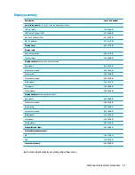
Fan/heat sink assembly

NOTE:

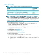
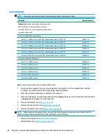
The heat sink assembly spare part kit includes replacement thermal materials.

Description

Spare part number

Fan/heat sink assembly for use in models with discrete graphics

858504-001

Fan/heat sink assembly for use in models with Intel Core processors and UMA graphics

856681-001

Fan/heat sink assembly for use in models with Intel Core processors and discrete graphics

856682-001

Fan/heat sink assembly for use in models with Intel Pentium or Celeron processors and UMA graphics

858503-001

NOTE:

To properly ventilate the computer, allow at least 7.6 cm (3.0 in) of clearance on the left side of the 

computer. The computer uses an electric fan for ventilation. The fan is controlled by a temperature sensor and 
is designed to turn on automatically when high temperature conditions exist. These conditions are affected by 
high external temperatures, system power consumption, power management/battery conservation 
configurations, battery fast charging, and software requirements. Exhaust air is displaced through the 
ventilation grill located on the left side of the computer.

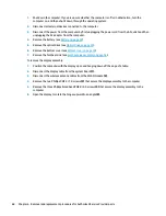
Before removing the heat sink assembly, follow these steps:

1.

Shut down the computer. If you are unsure whether the computer is off or in Hibernation, turn the 
computer on, and then shut it down through the operating system.

2.

Disconnect all external devices connected to the computer.

3.

Disconnect the power from the computer by first unplugging the power cord from the AC outlet and then 
unplugging the AC adapter from the computer.

4.

Remove the battery (see 

Battery on page 32

).

5.

Remove the optical drive (see 

Optical drive on page 33

).

6.

Remove the bottom cover (see 

Bottom cover on page 39

).

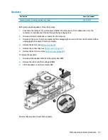
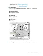
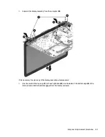
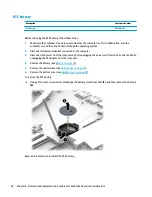
To remove the fan/heat sink assembly:

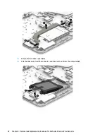
1.

If you have a model with discrete graphics and a fan integrated in the heat sink:

a.

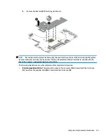
Disconnect the fan cable from the system board (1).

b.

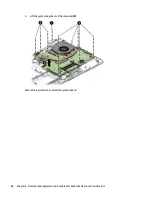
In the order indicated, remove the six Phillips PM2.0×3.0 screws (2) that secure the heat sink to the 
system board.

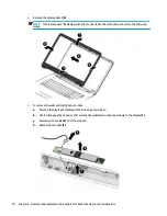
56

Chapter 6   Removal and replacement procedures for Authorized Service Provider parts

Содержание 17-x Series

Страница 1: ...HP Notebook PC Intel Models HP 17 x000 17 x099 Maintenance and Service Guide ...

Страница 2: ...soft s support please see Microsoft s Support Lifecycle FAQ at https support microsoft com lifecycle The information contained herein is subject to change without notice The only warranties for HP products and services are set forth in the express warranty statements accompanying such products and services Nothing herein should be construed as constituting an additional warranty HP shall not be li...

Страница 3: ...w another hard surface such as an adjoining optional printer or a soft surface such as pillows or rugs or clothing to block airflow Also do not allow the AC adapter to contact the skin or a soft surface such as pillows or rugs or clothing during operation The device and the AC adapter comply with the user accessible surface temperature limits defined by the International Standard for Safety of Inf...

Страница 4: ...iv Safety warning notice ...

Страница 5: ...y subcomponents 21 Miscellaneous parts 23 Mass storage devices 24 Cables 25 4 Removal and replacement procedures preliminary requirements 27 Tools required 27 Service considerations 27 Plastic parts 27 Cables and connectors 27 Drive handling 28 Grounding guidelines 28 Electrostatic discharge damage 28 Packaging and transporting guidelines 29 Workstation guidelines 29 5 Removal and replacement proc...

Страница 6: ... button board 76 Power connector 77 Cable locations 78 Top cover keyboard 79 7 Using Setup Utility BIOS in Windows 10 81 Starting Setup Utility BIOS 81 Updating Setup Utility BIOS 81 Determining the BIOS version 81 Downloading a BIOS update 82 8 Backing up restoring and recovering in Windows 10 83 Creating recovery media and backups 83 Creating HP Recovery media select products only 83 Using Windo...

Страница 7: ...cs UEFI to a USB device 89 10 Specifications 91 Computer specifications 91 43 9 cm 17 3 in display specifications 92 Hard drive specifications 92 DVD RW SuperMulti DL Drive specifications 93 11 Power cord set requirements 95 Requirements for all countries 95 Requirements for specific countries and regions 96 12 Recycling 99 Index 101 vii ...

Страница 8: ...viii ...

Страница 9: ... 56 GHz 2 MB L3 cache 1600 MHz quad 6W Intel Celeron N3060 1 6 GHz turbo up to 2 48 GHz 2 MB L3 cache 1600 MHz quad 6W Chipset Intel Skylake U 1 chip series Intel Broadwell U 1 chip BGA Intel Braswell Graphics Internal graphics Intel HD Graphics 5500 Intel Broadwell U series Intel HD Graphics 520 Intel Skylake U series Intel HD Graphics Intel Braswell series Support HD Decode DX12 HDMI and PX7 Swi...

Страница 10: ...el Memory One SODIMM slot customer accessible upgradeable DDR3L 1600 MHz single channel support 8192 MB total system memory 8192 1 4096 MB total system memory 4096 1 Two SODIMM slots customer accessible upgradeable DDR4 2133 MHz dual channel support 1 2V DDR3L 1600 MHz dual channel support 1 35V Supports up to 16 GB of system RAM in the following configurations 16384 MB total system memory 8192 2 ...

Страница 11: ...digital microphone HP Webcam VGA camera 640 480 by 24 frames per second Single digital microphone Audio Dual speakers DTS Studio Sound Ethernet Integrated 10 100 network interface card NIC Wireless networking Integrated Wireless options with dual antennas M 2 PCIe Intel Dual Band Wireless AC 3165 802 11 ac 1x1 WiFi BT 4 2 Combo Adapter Intel Dual Band Wireless AC 3168 802 11 ac 1x1 WiFi BT 4 2 Com...

Страница 12: ...ey pad TouchPad Image sensor Multitouch gestures enabled Taps enabled by default Support Modern Trackpad Gestures Power requirements Battery 4 cell 41 Whr 2 8Ah li ion battery 3 cell 31 Whr 2 8Ah li ion battery AC adapters AC Adapter 65 W Smart nPFC 3 pin RC 4 5mm connector models with discrete graphics only AC Adapter 65 W EM Smart nPFC 3 pin RC 4 5mm connector models with discrete graphics in In...

Страница 13: ...ent Cel Dis Pent Cel Dis 6th Gen Core UMA 6th Gen Core Windows 10 Home High End EM SL China CPPP Windows 10 Home China Language Edition FreeDOS 2 0 Windows 10 Home Value India Notebook Serviceability End user replaceable parts AC adapter Battery Optical drive 5 ...

Страница 14: ...6 Chapter 1 Product description ...

Страница 15: ...eaming video To use a webcam integrated camera Type camera in the taskbar search box and then select Camera 4 Internal microphone Records sound The antennas are not visible from the outside of the computer For optimal transmission keep the areas immediately around the antennas free from obstructions For wireless regulatory notices see the section of the Regulatory Safety and Environmental Notices ...

Страница 16: ... the card into the memory card reader and then press in on the card until it is firmly seated To remove a card Press in on the card and then remove it from the memory card reader 4 USB 2 0 port Connects an optional USB device such as a keyboard mouse external drive printer scanner or USB hub 5 Optical drive Depending on your computer reads an optical disc or reads and writes to an optical disc NOT...

Страница 17: ...k status lights Connects a network cable White The network is connected Amber Activity is occurring on the network 5 HDMI port Connects an optional video or audio device such as a high definition television any compatible digital or audio component or a high speed High Definition Multimedia Interface HDMI device 6 USB 3 0 port Connects an optional USB device such as a keyboard mouse external drive...

Страница 18: ...t All apps select HP Help and Support and then select HP Documentation NOTE When a device is connected to the jack the computer speakers are disabled Top TouchPad Component Description 1 TouchPad zone Reads your finger gestures to move the pointer or activate items on the screen 2 Left TouchPad button Functions like the left button on an external mouse 3 Right TouchPad button Functions like the ri...

Страница 19: ...Lights Component Description 1 Caps lock light On Caps lock is on which switches the key input to all capital letters 2 Mute light Amber Computer sound is off Off Computer sound is on Top 11 ...

Страница 20: ...it Hibernation CAUTION Pressing and holding down the power button results in the loss of unsaved information If the computer has stopped responding and shutdown procedures are ineffective press and hold the power button down for at least 5 seconds to turn off the computer To learn more about your power settings see your power options Type power in the taskbar search box and then select Power and s...

Страница 21: ...ows key Opens the Start menu NOTE Pressing the Windows key again will close the Start menu 4 Action keys Execute frequently used system functions NOTE On select products the f5 action key turns the keyboard feature off or on 5 num lock key Alternates between the navigational and numeric functions on the integrated numeric keypad 6 Integrated numeric keypad When num lock is on the keypad can be use...

Страница 22: ...repeatedly pressing this key alternates the screen image from the computer display to the monitor display to a simultaneous display on both the computer and the monitor Turns the keyboard backlight off or on select products only NOTE To conserve battery power turn off this feature Mutes or restores speaker sound Decreases speaker volume incrementally while you hold down the key Increases speaker v...

Страница 23: ...Bottom Component Description 1 Battery lock Locks the battery in the battery bay 2 Battery bay Holds the battery 3 Battery release latch Releases the battery 4 Speakers Produce sound Bottom 15 ...

Страница 24: ... that is unique to each product 3 Part number Product number p n This number provides specific information about the product s hardware components The part number helps a service technician to determine what components and parts are needed 4 Warranty period This number describes the duration of the warranty period for the computer 5 Model description This is the alphanumeric identifier used to loc...

Страница 25: ...TE HP continually improves and changes product parts For complete and current information on supported parts for your computer go to http partsurfer hp com select your country or region and then follow the on screen instructions Computer major components 17 ...

Страница 26: ... 856772 xx1 White silver 856773 xx1 Red 856775 xx1 Teal 856776 xx1 Blue 856777 xx1 3 USB board 856613 001 4 Power connector cable 856680 001 5 Power button board 856612 001 6 TouchPad board 858259 001 Heat sink assembly includes replacement thermal materials 7 For use in models with Intel Pentium or Celeron processors and UMA graphics 858503 001 8 For use in models with Intel Core processors and U...

Страница 27: ... Core processors Intel Pentium processors and Intel Celeron processors 8 GB 693374 005 4 GB 691740 005 2 GB 691739 005 PC4 17000 2133 MHz For use in models with 6th generation Intel Core processors 8 GB 820570 005 4 GB 820569 005 2 GB 851379 005 20 System board includes replacement thermal materials All system boards use the following part numbers xxxxxx 001 Windows 7 or non Windows operating syst...

Страница 28: ... i3 5005U processor 856692 xxx Intel Pentium N3710 processor 856694 xxx Intel Celeron N3060 processor 856695 xxx 21 Optical Drive Connector Cable Kit 856609 001 22 DVD RW Double Layer SuperMulti Drive 756564 037 Optical drive bracket not illustrated 856610 001 Optical drive bezel not illustrated 856598 001 23 Battery 4 cell 41 Whr 2 8 Ah Li ion 807957 001 3 cell 31 Whr 2 8 Ah Li ion 807956 001 24 ...

Страница 29: ...Display assembly subcomponents Display assembly subcomponents 21 ...

Страница 30: ...ouch displays 856607 001 6 Antennas 856611 001 7 Touch control board 856600 001 8 Webcam microphone module HD 709372 032 VGA 766523 021 9 Display enclosure non touch models Red models 856594 001 White silver models 856593 001 Blue models 856596 001 Turbo silver models 856592 001 Black models 856591 001 Teal models 856595 001 Purple models 900660 001 9 Display enclosure touch models Red models 8565...

Страница 31: ...tries Portugal Greece Arabia the Netherlands Belgium Russia Bulgaria Romania Poland Hungary Serbia Adriatic countries Czech Slovakia African English 213350 009 India 404827 003 Israel 398063 003 Japan 349756 002 North America 213349 009 South Korea 267836 008 Switzerland 213354 008 The United Kingdom Arabia African English Hong Kong 213351 008 Rubber Kit includes front and rear feet 856615 001 Scr...

Страница 32: ...l drive connector 856609 001 5 Hard drive does not include bracket 2 TB 5400 rpm 2 5 inch 801808 005 1 TB 5400 rpm 2 5 inch hybrid 8 GB SSD 731999 005 1 TB 5400 rpm 2 5 in 778192 005 500 GB 5400 rpm 2 5 inch 778188 005 6 Hard drive cover 856584 001 7 Solid state drive board 856614 001 8 Solid state drive holder 858260 001 9 Solid state drive 24 Chapter 3 Illustrated parts catalog ...

Страница 33: ...003 128 GB 827560 025 Cables Item Description Spare part number 1 TouchPad cable 856605 001 2 Touch click board cable 856606 001 3 Power button board cable 856604 001 4 USB board cable 856603 001 5 Optical drive connector cable 856609 001 Cables 25 ...

Страница 34: ...26 Chapter 3 Illustrated parts catalog ...

Страница 35: ... and reassembly can damage plastic parts Use care when handling the plastic parts Apply pressure only at the points designated in the maintenance instructions Cables and connectors CAUTION When servicing the computer be sure that cables are placed in their proper locations during the reassembly process Improper cable placement can damage the computer Cables must be handled with extreme care to avo...

Страница 36: ... Electronic components are sensitive to electrostatic discharge ESD Circuitry design and structure determine the degree of sensitivity Networks built into many integrated circuits provide some protection but in many cases ESD contains enough power to alter device parameters or melt silicon junctions A discharge of static electricity from a finger or other conductor can destroy static sensitive dev...

Страница 37: ...ly Store reusable ESD sensitive parts from assemblies in protective packaging or non conductive foam Use transporters and conveyors made of antistatic belts and roller bushings Be sure that mechanized equipment used for moving materials is wired to ground and that proper materials are selected to avoid static charging When grounding is not possible use an ionizer to dissipate electric charges Work...

Страница 38: ...operator and ground To be effective the conductive must be worn in contact with the skin The following grounding equipment is recommended to prevent electrostatic damage Antistatic tape Antistatic smocks aprons and sleeve protectors Conductive bins and other assembly or soldering aids Nonconductive foam Conductive tabletop workstations with ground cords of one megohm resistance Static dissipative ...

Страница 39: ...our country or region and then follow the on screen instructions Component replacement procedures NOTE Please read and follow the procedures described here to access and replace Customer Self Repair parts successfully NOTE Details about your computer including model serial number product key and length of warranty are on the service tag at the bottom of your computer This chapter provides removal ...

Страница 40: ...evices connected to the computer 3 Disconnect the power from the computer by first unplugging the power cord from the AC outlet and then unplugging the AC adapter from the computer To remove the battery 1 Position the computer upside down on a flat surface 2 Slide the battery lock latch 1 to unlock the battery and then slide the battery release latch 2 to release the battery NOTE The battery relea...

Страница 41: ...n and then shut it down through the operating system 2 Disconnect all external devices connected to the computer 3 Disconnect the power from the computer by first unplugging the power cord from the AC outlet and then unplugging the AC adapter from the computer 4 Remove the battery see Battery on page 32 To remove the optical drive 1 Remove the Phillips PM2 5 8 0 screw 1 that secures the optical dr...

Страница 42: ...optical drive remove the Phillips PM2 0 2 5 screw 1 that secures the bracket to the drive and then remove the bracket 2 Reverse this procedure to reassemble and install the optical drive 34 Chapter 5 Removal and replacement procedures for Customer Self Repair parts ...

Страница 43: ...rews that must be removed replaced or loosened when servicing Authorized Service Provider only parts Make special note of each screw size and location during removal and replacement Display subcomponents bezel webcam panel This section describes removing display subcomponents that do not require that you remove the entire display assembly from the computer You can remove the display bezel webcam m...

Страница 44: ... battery see Battery on page 32 To remove the display bezel webcam microphone module and raw display panel 1 Position the computer upright with the front toward you and then open it 2 Flex the inside of the top edge 1 left and right sides 2 and the inside of the bottom edge 3 of the display bezel until the bezel disengages from the display enclosure 3 Remove the display bezel 4 4 To remove the web...

Страница 45: ...el to the enclosure b Rotate the display panel onto the keyboard 2 to gain access to the display cable connection on the back of the panel c On the back of the display panel release the adhesive strip that secures the display panel cable to the display panel and then disconnect the cable 1 Component replacement procedures 37 ...

Страница 46: ... panel from the computer 2 Reverse this procedure to reassemble and install the display bezel webcam microphone module and display panel 38 Chapter 6 Removal and replacement procedures for Authorized Service Provider parts ...

Страница 47: ...om the AC outlet and then unplugging the AC adapter from the computer 4 Remove the battery see Battery on page 32 5 Remove the optical drive see Optical drive on page 33 To remove the bottom cover 1 Position the computer upside down with the front toward you 2 Remove the two rubber feet 1 3 Remove the service label screw cutouts from above the two screws under the label 2 NOTE Two screws that are ...

Страница 48: ...f the computer and pry to separate the bottom cover from the computer 1 Work your way around prying to disengage the bottom cover from the computer and then remove the cover 2 Reverse this procedure to install the bottom cover 40 Chapter 6 Removal and replacement procedures for Authorized Service Provider parts ...

Страница 49: ...m 2 Disconnect all external devices connected to the computer 3 Disconnect the power from the computer by first unplugging the power cord from the AC outlet and then unplugging the AC adapter from the computer 4 Remove the battery see Battery on page 32 5 Remove the optical drive see Optical drive on page 33 6 Remove the bottom cover see Bottom cover on page 39 To remove the hard drive 1 Remove th...

Страница 50: ...2 Rotate the hard drive upward 1 3 Pull the drive away from the connector and then remove it from the computer 2 42 Chapter 6 Removal and replacement procedures for Authorized Service Provider parts ...

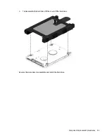
Страница 51: ...4 To disassemble the hard drive lift the cover off the hard drive Reverse this procedure to reassemble and install the hard drive Component replacement procedures 43 ...

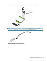
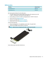
Страница 52: ...omputer If you are unsure whether the computer is off or in Hibernation turn the computer on and then shut it down through the operating system 2 Disconnect all external devices connected to the computer 3 Disconnect the power from the computer by first unplugging the power cord from the AC outlet and then unplugging the AC adapter from the computer 4 Remove the battery see Battery on page 32 5 Re...

Страница 53: ...le 3 NOTE If the WLAN antennas are not connected to the terminals on the WLAN module the protective sleeves must be installed on the antenna connectors as shown in the following illustration Reverse this procedure to install the WLAN module Component replacement procedures 45 ...

Страница 54: ...he power from the computer by first unplugging the power cord from the AC outlet and then unplugging the AC adapter from the computer 4 Remove the battery see Battery on page 32 5 Remove the optical drive see Optical drive on page 33 6 Remove the bottom cover see Bottom cover on page 39 To remove the RTC battery Using a thin tool or screwdriver disengage the battery from the socket 1 and then remo...

Страница 55: ...sure whether the computer is off or in Hibernation turn the computer on and then shut it down through the operating system 2 Disconnect all external devices connected to the computer 3 Disconnect the power from the computer by first unplugging the power cord from the AC outlet and then unplugging the AC adapter from the computer 4 Remove the battery see Battery on page 32 5 Remove the optical driv...

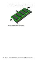
Страница 56: ...move the memory module 2 by pulling it away from the slot at an angle Reverse this procedure to install a memory module 48 Chapter 6 Removal and replacement procedures for Authorized Service Provider parts ...

Страница 57: ...from the computer by unplugging the power cord from the computer 3 Remove the battery see Battery on page 32 4 Remove the optical drive see Optical drive on page 33 5 Remove the bottom cover see Bottom cover on page 39 Remove the solid state drive 1 Remove the Phillips PM2 0 2 0 screw 1 that secures the drive to the system board 2 Remove the drive 2 by pulling it away from the connector NOTE Solid...

Страница 58: ...g the AC adapter from the computer 4 Remove the battery see Battery on page 32 5 Remove the optical drive see Optical drive on page 33 6 Remove the bottom cover see Bottom cover on page 39 7 Remove the solid state drive see Solid state drive on page 49 To remove the solid state drive holder and board 1 Remove the Phillips PM2 0 4 5 screws 1 that secures the solid state drive holder to the computer...

Страница 59: ...4 Lift the board out of the holder 2 Reverse this procedure to install the solid state drive holder and board Component replacement procedures 51 ...

Страница 60: ...power cord from the AC outlet and then unplugging the AC adapter from the computer 4 Remove the battery see Battery on page 32 5 Remove the optical drive see Optical drive on page 33 6 Remove the bottom cover see Bottom cover on page 39 To remove the optical drive connector 1 Disconnect the optical drive connector cable from the system board 1 2 Remove the Phillips PM2 0 3 0 screw 2 that secures t...

Страница 61: ...r 3 Disconnect the power from the computer by first unplugging the power cord from the AC outlet and then unplugging the AC adapter from the computer 4 Remove the battery see Battery on page 32 5 Remove the optical drive see Optical drive on page 33 6 Remove the bottom cover see Bottom cover on page 39 To remove the TouchPad click board 1 Disconnect the cables from the TouchPad cable 1 and the Tou...

Страница 62: ...r by first unplugging the power cord from the AC outlet and then unplugging the AC adapter from the computer 4 Remove the battery see Battery on page 32 5 Remove the optical drive see Optical drive on page 33 6 Remove the bottom cover see Bottom cover on page 39 To remove the USB board 1 Disconnect the cable from the USB board 1 2 Remove the Phillips PM2 0 4 0 screw 2 that secures the USB board to...

Страница 63: ...the computer 3 Disconnect the power from the computer by first unplugging the power cord from the AC outlet and then unplugging the AC adapter from the computer 4 Remove the battery see Battery on page 32 5 Remove the optical drive see Optical drive on page 33 6 Remove the bottom cover see Bottom cover on page 39 To remove the speakers 1 Disconnect the speaker cable from the system board 1 2 Remov...

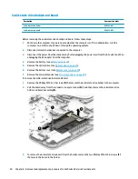
Страница 64: ...nservation configurations battery fast charging and software requirements Exhaust air is displaced through the ventilation grill located on the left side of the computer Before removing the heat sink assembly follow these steps 1 Shut down the computer If you are unsure whether the computer is off or in Hibernation turn the computer on and then shut it down through the operating system 2 Disconnec...

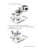
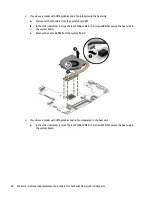
Страница 65: ...model with discrete graphics and no fan integrated in the heat sink a In the order indicated remove the four Phillips PM2 0 3 0 screws 1 that secure the heat sink to the system board b Remove the heat sink 2 from the system board Component replacement procedures 57 ...

Страница 66: ... 3 0 screws 2 that secure the heat sink to the system board c Remove the heat sink 3 from the system board 4 If you have a model with UMA graphics and no fan integrated in the heat sink a In the order indicated remove the four Phillips PM2 0 3 0 screws 1 that secure the heat sink to the system board 58 Chapter 6 Removal and replacement procedures for Authorized Service Provider parts ...

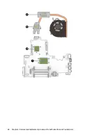
Страница 67: ...k is removed Replacement thermal material is included with the heat sink processor and system board spare part kits The following illustrations show the replacement thermal material locations Discrete graphics with fan Thermal paste is used on the processor 1 and associated heat sink area 2 as well as the graphics chip 3 and associated heat sink area 4 Component replacement procedures 59 ...

Страница 68: ...60 Chapter 6 Removal and replacement procedures for Authorized Service Provider parts ...

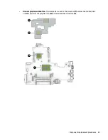
Страница 69: ... Discrete graphics without fan Thermal paste is used on the processor 1 and associated heat sink area 2 as well as the graphics chip 3 and associated heat sink area 4 Component replacement procedures 61 ...

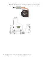
Страница 70: ... UMA graphics with fan Thermal paste is used on the processor 1 and associated heat sink area 2 62 Chapter 6 Removal and replacement procedures for Authorized Service Provider parts ...

Страница 71: ...MA graphics without fan Thermal paste is used on the processor 1 and associated heat sink area 2 Reverse this procedure to reassemble and install the heat sink assembly Component replacement procedures 63 ...

Страница 72: ...xx Intel Core i5 6200U processor 856684 xxx Intel Core i3 6100U processor 856683 xxx Intel Core i3 5005U processor 856692 xxx Intel Pentium N3710 processor 856694 xxx Intel Celeron N3060 processor 856695 xxx Before removing the system board follow these steps 1 Shut down the computer If you are unsure whether the computer is off or in Hibernation turn the computer on and then shut it down through ...

Страница 73: ...s from the system board 1 Keyboard cable 2 Keyboard backlight cable 3 Optical drive connector cable 4 USB board cable 5 TouchPad cable 6 Power connector cable 7 Display cable 8 Power button board 9 Speaker cable 2 Remove the Phillips PM2 0 3 0 screw 1 that secures the system board to the computer 3 Remove the eight Phillips PM2 5 7 0 screws 2 that secure the system board to the computer Component ...

Страница 74: ...4 Lift the system board out of the computer 3 Reverse this procedure to install the system board 66 Chapter 6 Removal and replacement procedures for Authorized Service Provider parts ...

Страница 75: ...hite silver models 856593 001 Blue models 856596 001 Turbo silver models 856592 001 Black models 856591 001 Teal models 856595 001 Purple models 900660 001 Display enclosure for use in touch models Red models 856588 001 White silver models 856587 001 Blue models 856590 001 Turbo silver models 856586 001 Black models 856585 001 Teal models 856589 001 Purple models 900659 001 Hinges left and right 8...

Страница 76: ...tom cover see Bottom cover on page 39 7 Remove the fan heat sink see Fan heat sink assembly on page 56 To remove the display assembly 1 Position the computer with the display open and hanging down off the edge of a table 2 Disconnect the display cable from the system board 1 3 Disconnect the wireless antenna cables from the WLAN module 2 4 Remove the two Phillips PM2 5 7 0 screws 3 that secure the...

Страница 77: ...essary to replace any of the display assembly subcomponents 1 Flex the inside of the top edge 1 left and right sides 2 and the inside of the bottom edge 3 of the display bezel until the bezel disengages from the display enclosure Component replacement procedures 69 ...

Страница 78: ...o remove the webcam microphone module a Position the display assembly with the top edge toward you b Lift to disengage the adhesive that secures the webcam microphone module to the display 1 c Disconnect the cable 2 from the module d Remove the module 3 70 Chapter 6 Removal and replacement procedures for Authorized Service Provider parts ...

Страница 79: ...d 2 to gain access to the display cable connection on the back of the panel NOTE In this procedure the display will not be connected to the computer as shown in the following image c On the back of the display panel release the adhesive strip that secures the display panel cable to the display panel and then disconnect the cable 1 Component replacement procedures 71 ...

Страница 80: ...e the touch control board from the display a Remove the two Phillips PM2 0 2 0 screws 1 that secure the touch control board to the top of the display assembly b Rotate the board upside down to access the connectors underneath 2 c Disconnect the cable from the end of the board 1 72 Chapter 6 Removal and replacement procedures for Authorized Service Provider parts ...

Страница 81: ...ch control board from the display assembly 3 6 To remove the display hinges a Remove the three Phillips broadhead PM2 5 3 0 screws 1 from the bottom of each hinge and the Phillips broadhead PM2 5 3 0 screw 2 from the top of each hinge Component replacement procedures 73 ...

Страница 82: ...elease the wireless antenna cables from the clips 1 built into the back of the display peel off the transceivers 2 and then remove the antenna cables and transceivers 3 NOTE Number of antennas and transceivers may vary 74 Chapter 6 Removal and replacement procedures for Authorized Service Provider parts ...

Страница 83: ...mponents including the webcam microphone module the antenna receivers and all associated cables and hardware are transferred to the new enclosure Reverse this procedure to reassemble and install the display assembly When reassembling and reinstalling the display assembly note the routing of the antenna cable 1 and display webcam cable 2 as shown in the following image Component replacement procedu...

Страница 84: ... then unplugging the AC adapter from the computer 4 Remove the battery see Battery on page 32 5 Remove the optical drive see Optical drive on page 33 6 Remove the bottom cover see Bottom cover on page 39 7 Remove the fan heat sink see Fan heat sink assembly on page 56 8 Remove the display see Display assembly on page 67 To remove the power button board 1 Disconnect the cable from the power button ...

Страница 85: ... by first unplugging the power cord from the AC outlet and then unplugging the AC adapter from the computer 4 Remove the battery see Battery on page 32 5 Remove the optical drive see Optical drive on page 33 6 Remove the bottom cover see Bottom cover on page 39 7 Remove the fan heat sink see Fan heat sink assembly on page 56 8 Remove the display see Display assembly on page 67 To remove the power ...

Страница 86: ...001 TouchPad cable 856605 001 Touch click board cable 856606 001 Use the following image to determine proper cable routing in the computer 1 Power button board cable 2 Optical drive cable 3 USB board cable 4 TouchPad cable 5 TouchPad click board cable 78 Chapter 6 Removal and replacement procedures for Authorized Service Provider parts ...

Страница 87: ...ard Black 856771 xx1 Turbo silver 856772 xx1 White silver 856773 xx1 Red 856775 xx1 Teal 856776 xx1 Blue 856777 xx1 Purple 900154 xx1 For use in country or region Spare part number For use in country or region Spare part number For use in country or region Spare part number Belgium A41 Greece 151 Saudi Arabia 171 Bulgaria 261 Hungary 211 Slovenia BA1 Canada DB1 Israel BB1 South Korea AD1 Czech Rep...

Страница 88: ...cludes the keyboard keyboard cable and the keyboard backlight cable The top cover keyboard spare part remains after all other spare parts have been removed 80 Chapter 6 Removal and replacement procedures for Authorized Service Provider parts ...

Страница 89: ...vailable on the HP website Most BIOS updates on the HP website are packaged in compressed files called SoftPaqs Some download packages contain a file named Readme txt which contains information regarding installing and troubleshooting the file Determining the BIOS version To decide whether you need to update Setup Utility BIOS first determine the BIOS version on your computer To reveal the BIOS ve...

Страница 90: ...ost recent BIOS update and compare it to the BIOS version currently installed on your computer If the update is more recent than your BIOS version make a note of the date name or other identifier You may need this information to locate the update later after it has been downloaded to your hard drive b Follow the on screen instructions to download your selection to the hard drive Make a note of the...

Страница 91: ...ckup of the HP Recovery partition on the computer The backup can be used to reinstall the original operating system in cases where the hard drive is corrupted or has been replaced For information on creating recovery media see Creating HP Recovery media select products only on page 83 For information on the recovery options that are available using the recovery media see Using Windows tools on pag...

Страница 92: ...to create recovery discs If you use an external optical drive it must be connected directly to a USB port on the computer the drive cannot be connected to a USB port on an external device such as a USB hub If you cannot create DVD media yourself you can obtain recovery discs for your computer from HP See the Worldwide Telephone Numbers booklet included with the computer You can also find contact i...

Страница 93: ...o remove the recovery partition to reclaim hard drive space HP Recovery Manager offers the Remove Recovery Partition option For more information see Removing the HP Recovery partition select products only on page 87 Recovering using HP Recovery Manager HP Recovery Manager software allows you to recover the computer to its original factory state by using the HP Recovery media that you either create...

Страница 94: ...o start HP Recovery Manager from the HP Recovery partition IMPORTANT For a tablet with a detachable keyboard connect the keyboard to the keyboard dock before beginning these steps select products only 1 Type recovery in the taskbar search box select Recovery Manager and then select HP Recovery Environment or For computers or tablets with keyboards attached press f11 while the computer boots or pre...

Страница 95: ...tart the tablet and then quickly hold down the Windows button then select f9 3 Select the optical drive or USB flash drive from which you want to boot 4 Follow the on screen instructions Removing the HP Recovery partition select products only HP Recovery Manager software allows you to remove the HP Recovery partition to free up hard drive space IMPORTANT After you remove the HP Recovery partition ...

Страница 96: ...88 Chapter 8 Backing up restoring and recovering in Windows 10 ...

Страница 97: ...lowing order a Connected USB drive NOTE To download the HP PC Hardware Diagnostics UEFI tool to a USB drive see Downloading HP PC Hardware Diagnostics UEFI to a USB device on page 89 b Hard drive c BIOS 3 When the diagnostic tool opens select the type of diagnostic test you want to run and then follow the on screen instructions NOTE If you need to stop a diagnostic test press esc Downloading HP PC...

Страница 98: ...let HP automatically detect your product 4 Select your computer and then select your operating system 5 In the Diagnostic section follow the on screen instructions to select and download the UEFI version you want 90 Chapter 9 Using HP PC Hardware Diagnostics UEFI ...

Страница 99: ... 3 5 A or 19 5 V dc 3 33 A 65 W Temperature Operating 5 C to 35 C 41 F to 95 F Nonoperating 20 C to 60 C 4 F to 140 F Relative humidity noncondensing Operating 10 to 90 Nonoperating 5 to 95 Maximum altitude unpressurized Operating 15 m to 3 048 m 50 ft to 10 000 ft Nonoperating 15 m to 12 192 m 50 ft to 40 000 ft NOTE Applicable product safety standards specify thermal limits for plastic surfaces ...

Страница 100: ... mm Weight 115 0 g 115 0 g 92 0 g Interface type SATA SATA SATA Transfer rate Synchronous maximum 300 MB sec 300 MB sec 300 MB sec Security ATA security ATA security ATA security Seek times typical read including setting Single track 1 4 ms 1 4 ms 3 ms Average read write 10 ms 10 ms 13 ms Maximum 12 ms 12 ms 24 ms Logical blocks 3 877 842 922 1 938 921 461 1 048 576 000 Disk rotational speed 5400 ...

Страница 101: ...iameter Standard disc 12 cm 4 72 in Mini disc 8 cm 3 15 in Disc thickness 1 2 mm 0 047 in Track pitch 0 74 µm Access time CD DVD Random 175 ms 230 ms Full stroke 285 ms 335 ms Audio output level Line out 0 7 Vrms Cache buffer 2 MB Data transfer rate 24X CD ROM 3 600 KB sec 8X DVD ROM 10 800 KB sec 24X CD R 3 600 KB sec 16X CD RW 2 400 KB sec 8X DVD R 10 800 KB sec 4X DVD RW 5 400 KB sec 8X DVD R 1...

Страница 102: ...94 Chapter 10 Specifications ...

Страница 103: ...ng requirements are applicable to all countries and regions The length of the power cord set must be at least 1 5 m 5 0 ft and no more than 2 0 m 6 5 ft All power cord sets must be approved by an acceptable accredited agency responsible for evaluation in the country or region where the power cord set will be used The power cord sets must have a minimum current capacity of 10 A and a nominal voltag...

Страница 104: ...orea KTL 5 Sweden SEMKO 1 Switzerland SEV 1 Taiwan BSMI 6 Thailand TISI 1 The United Kingdom ASTA 1 The United States UL 2 1 The flexible cord must be Type HO5VV F 3 conductor 0 75mm2 conductor size Power cord set fittings appliance coupler and wall plug must bear the certification mark of the agency responsible for evaluation in the country or region where it will be used 2 The flexible cord must...

Страница 105: ...wall plug must bear the CCC certification mark 5 The flexible cord must be Type H05VV F 3X0 75mm2 conductor size KTL logo and individual approval number must be on each element Corset approval number and logo must be printed on a flag label 6 The flexible cord must be Type HVCTF 3X1 25mm2 conductor size Power cord set fittings appliance coupler cable and wall plug must bear the BSMI certification ...

Страница 106: ...98 Chapter 11 Power cord set requirements ...

Страница 107: ...he battery in general household waste Follow the local laws and regulations in your area for battery disposal HP encourages customers to recycle used electronic hardware HP original print cartridges and rechargeable batteries For more information about recycling programs see the HP Web site at http www hp com recycle 99 ...

Страница 108: ...100 Chapter 12 Recycling ...

Страница 109: ... assembly illustrated 18 removing 35 67 spare part numbers 18 display assembly subcomponents illustrated 21 removing 35 67 display bezel illustrated 22 removing 36 69 display cable illustrated 22 removing 75 display enclosure illustrated 22 removing 75 display panel illustrated 22 67 product description 2 removing 37 71 display specifications 92 drive light 8 DVD RW SuperMulti DL Drive specificati...

Страница 110: ...rear bracket removing 34 optical drive identifying 8 original system recovery 85 P packaging guidelines 29 plastic parts service considerations 27 pointing device 4 ports HDMI 9 product description 4 USB 2 0 8 9 USB 3 0 9 power button board illustrated 18 removing 76 power button identifying 12 power connector cable illustrated 18 removing 77 power connector identifying 9 power cord requirements f...

Страница 111: ...number 19 64 system recovery 85 system restore point creating 84 system restore point creating 83 T tools required 27 top cover illustrated 18 top cover keyboard 79 touch control board illustrated 22 removing 72 spare part number 67 TouchPad buttons 10 TouchPad board illustrated 18 TouchPad click board removing 53 spare part number 53 TouchPad zone identifying 10 transporting guidelines 29 U USB 2...

Страница 112: ...104 Index ...
Отзывы: