16
16
E1CG4880210
E1CG4880210
COM
COM..
N.O.
N.O.
N.C.
N.C.
DEFROST
DEFROST
FREEZE
FREEZE
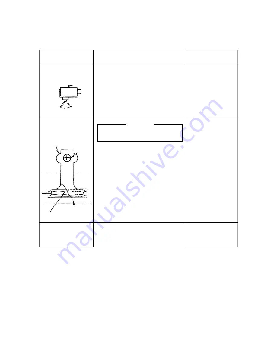
Holder
Holder
Screw
Screw
Thermistor
Thermistor
Evaporator
Evaporator
[b] BEFORE CHECKING CONTROLLER BOARD
[b] BEFORE CHECKING CONTROLLER BOARD
Check the power source voltage and the components as shown in the table below.
Check the power source voltage and the components as shown in the table below.
Component
Component
1. Actuator Toggle
1. Actuator Toggle
Switch
Switch
2. Thermistor
2. Thermistor
(on Evaporator)
(on Evaporator)
3. Bin Control Switch
3. Bin Control Switch
Procedure
Procedure
Manually set the switch in the FREEZE
Manually set the switch in the FREEZE
and DEFROST positions, and check the
and DEFROST positions, and check the
continuity.
continuity.
CAUTION
CAUTION
Thermistor Sensor part is fragile,
Thermistor Sensor part is fragile,
glass sealed. Handle with care.
glass sealed. Handle with care.
* Disconnect the Connector K4 on the
* Disconnect the Connector K4 on the
board.
board.
* Remove the screw and the Thermistor
* Remove the screw and the Thermistor
Holder on the Evaporator.
Holder on the Evaporator.
* Immerse the Sensor part in a glass
* Immerse the Sensor part in a glass
containing ice and water for 5 minutes.
containing ice and water for 5 minutes.
* Check the resistance between K4
* Check the resistance between K4
Connector Pins.
Connector Pins.
* Replace the Thermistor in its correct
* Replace the Thermistor in its correct
position.
position.
* Connect K4.
* Connect K4.
Manually set the Micro Switch in the
Manually set the Micro Switch in the
TRIP and RESET positions, and check
TRIP and RESET positions, and check
the period.
the period.
Normal
Normal
DEFROST
DEFROST
COM-NO
COM-NO
Open
Open
COM-NC
COM-NC
Close
Close
FREEZE
FREEZE
COM-NO
COM-NO
Close
Close
COM-NC
COM-NC
Open
Open
5 -7 kilohms
5 -7 kilohms
Approx.
Approx.
TRIP(Closed)
TRIP(Closed) 10 sec.
10 sec.
RESET(Open)
RESET(Open) 80 sec.
80 sec.
Содержание IM-240AME
Страница 6: ...2 2 E1CG4880210 E1CG4880210 b IM 240DWME Water cooled b IM 240DWME Water cooled ...
Страница 7: ...3 3 E1CG4880210 E1CG4880210 c IM 240DSME Remote Air cooled c IM 240DSME Remote Air cooled ...
Страница 8: ...4 4 E1CG4880210 E1CG4880210 d IM 240XME Air cooled d IM 240XME Air cooled ...
Страница 9: ...5 5 E1CG4880210 E1CG4880210 e IM 240XWME Water cooled e IM 240XWME Water cooled ...
Страница 10: ...6 6 E1CG4880210 E1CG4880210 f IM 240XSME Remote Air cooled f IM 240XSME Remote Air cooled ...
Страница 11: ...7 7 E1CG4880210 E1CG4880210 g IM 240AME Air cooled g IM 240AME Air cooled ...
Страница 61: ...57 57 E1CG4880210 E1CG4880210 2 WIRING DIAGRAM 2 WIRING DIAGRAM a IM 240DME IM 240XME a IM 240DME IM 240XME ...
Страница 62: ...58 58 E1CG4880210 E1CG4880210 b IM 240DWME IM 240XWME b IM 240DWME IM 240XWME ...
Страница 63: ...59 59 E1CG4880210 E1CG4880210 c IM 240DSME IM 240XSME c IM 240DSME IM 240XSME ...
Страница 64: ...60 60 E1CG4880210 E1CG4880210 d IM 240AME d IM 240AME ...
Страница 93: ...89 89 E1CG4880210 E1CG4880210 Fig 54 Fig 54 ...


