


44
44
E1CG4880210
E1CG4880210
Fig. 36
Fig. 36
[Normal Position]
[Normal Position]
[Drain Position]
[Drain Position]
Screw
Screw
Bracket
Bracket
Tank Drain
Tank Drain
Pipe
Pipe
2. PREPARING THE ICEMAKER FOR LONG STORAGE
2. PREPARING THE ICEMAKER FOR LONG STORAGE
WARNING
WARNING
Drain the icemaker to prevent damage to the water supply line at subfreezing
Drain the icemaker to prevent damage to the water supply line at subfreezing
temperatures, using air or carbon dioxide. Shut off the icemaker until proper air
temperatures, using air or carbon dioxide. Shut off the icemaker until proper air
temperature is resumed.
temperature is resumed.
1) Close the water supply tap, and remove the
1) Close the water supply tap, and remove the
Inlet Hose.
Inlet Hose.
2) Remove the Front Panel.
2) Remove the Front Panel.
3) Remove the screw located on the front of
3) Remove the screw located on the front of
the Water Tank.
the Water Tank.
4) Move the Tank Drain Pipe to the drain
4) Move the Tank Drain Pipe to the drain
position. See Fig. 36.
position. See Fig. 36.
5) Push the Reset Switch in the Control Box, or
5) Push the Reset Switch in the Control Box, or
disconnect power source and reconnect
disconnect power source and reconnect
after 3 minutes.
after 3 minutes.
6) The Water Pan will open, and then the
6) The Water Pan will open, and then the
Actuator Toggle Switch will turn to the
Actuator Toggle Switch will turn to the
“DEFROST” position in 40 seconds. (Click
“DEFROST” position in 40 seconds. (Click
sound will be heard.)
sound will be heard.)
7) Blow out the water supply line immediately
7) Blow out the water supply line immediately
after the Water Pan has opened.
after the Water Pan has opened.
Note: This procedure is necessary to protect the icemaker from freezing up at subfreezing
Note: This procedure is necessary to protect the icemaker from freezing up at subfreezing
temperature.
temperature.
8) Unplug the icemaker or disconnect the power source with the Actuator Toggle Switch in
8) Unplug the icemaker or disconnect the power source with the Actuator Toggle Switch in
the “DEFROST” position.
the “DEFROST” position.
9) Move the Tank Drain Pipe to the normal position, and secure it with the screw.
9) Move the Tank Drain Pipe to the normal position, and secure it with the screw.
10) Remove all ice from the Storage Bin, and clean the Bin.
10) Remove all ice from the Storage Bin, and clean the Bin.
11) Replace the panels in their correct positions.
11) Replace the panels in their correct positions.
12) Replace the Inlet Hose in its correct position.
12) Replace the Inlet Hose in its correct position.
Содержание IM-240AME
Страница 6: ...2 2 E1CG4880210 E1CG4880210 b IM 240DWME Water cooled b IM 240DWME Water cooled ...
Страница 7: ...3 3 E1CG4880210 E1CG4880210 c IM 240DSME Remote Air cooled c IM 240DSME Remote Air cooled ...
Страница 8: ...4 4 E1CG4880210 E1CG4880210 d IM 240XME Air cooled d IM 240XME Air cooled ...
Страница 9: ...5 5 E1CG4880210 E1CG4880210 e IM 240XWME Water cooled e IM 240XWME Water cooled ...
Страница 10: ...6 6 E1CG4880210 E1CG4880210 f IM 240XSME Remote Air cooled f IM 240XSME Remote Air cooled ...
Страница 11: ...7 7 E1CG4880210 E1CG4880210 g IM 240AME Air cooled g IM 240AME Air cooled ...
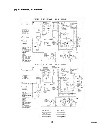
Страница 61: ...57 57 E1CG4880210 E1CG4880210 2 WIRING DIAGRAM 2 WIRING DIAGRAM a IM 240DME IM 240XME a IM 240DME IM 240XME ...
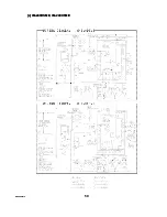
Страница 62: ...58 58 E1CG4880210 E1CG4880210 b IM 240DWME IM 240XWME b IM 240DWME IM 240XWME ...
Страница 63: ...59 59 E1CG4880210 E1CG4880210 c IM 240DSME IM 240XSME c IM 240DSME IM 240XSME ...
Страница 64: ...60 60 E1CG4880210 E1CG4880210 d IM 240AME d IM 240AME ...
Страница 93: ...89 89 E1CG4880210 E1CG4880210 Fig 54 Fig 54 ...