background image

GPS PC-board 6038

hopf 

hopf 

Elektronik

version 03.01

page 6

2 Introduction

The well-proved 

hopf

hopf

__

radio controlled / crystal clock systems have been extended by the GPS

1

reception unit which guarantees high precision running of the clock anywhere in the world.

The time basis is synchronised by the global satellite navigation system GPS. At a height of
about 20.000 km, satellites circle on different orbits and angles around the earth twice a day
(see picture in the appendix GPS). On board each satellite there is a high precision atomic clock
(precision min. 1x 10E-12). The GPS reception unit receives the orbit position and a GPS-world
time from as many satellites as possible. From these data first the position of the receiver is de-
termined. Once the position has been calculated the travel time of the transmission-information
from the individual satellites can be worked out. The accuracy of the time depends above all on
how accurately the position is calculated.

The world time UTC

2

 is calculated by subtracting the leap second from the GPS-world time

(GPS-UTC). At present (1994) the world time is 8 seconds slower than the GPS-UTC. The dif-
ference changes with the insertion of leap seconds. By means of the system key pad or serial
interface the difference to UTC and the regional time changeover for summer- / winter time can
be entered for any location in the world, which offers the local time for further use at high preci-
sion.

Different well-proved ways of communication like:

• 

8-Bit ISA-Bus interface via Dual-Port RAM

• 

serial RS232 interface

• 

PPS-pulse

are available. Also a DCF77-simulation of the local or UTC-time is integrated so that all

hopf

hopf

__

DCF77 radio controlled clocks can be controlled from here.

3 Starting


the Radio Clock Circuit Board 6038

When installing the radio controlled clock the computer and all the connected devices should be
switched off. Open the computer housing, plug the radio controlled clock into a vacant extension
space (8-bit ISA slot), connect the antenna and the clock is ready for operation.

After installation you have to control that there is no contact to any other board plugged in.

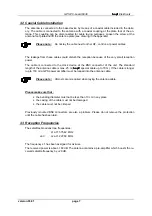
3.1 Antenna Installation

To guarantee a GPS-reception as constant as possible, the antenna must have free "view“ of
the whole horizon. The antenna is dimensioned so that it covers satellites over 10° above the
horizon. It requires the reception of 4 satellites to evaluate the position and time (3D mode). If
the view to a part of the sky is blocked by buildings, the GPS-receiver cannot evaluate the exact
time. It will wait until 4 satellites have moved into the free range of view. This can take up to four
hours in case of an unfavourable satellite constellation. Therefore the antenna should be placed
at the highest possible point on the roof (see drawing in the appendix). The quality of the re-
ceived satellites can be supervised by the programme 

"SERVICE.EXE"

 (see below).


1

 GPS = Global positioning system

2

 UTC = Universal time coordinated

Содержание 6038

Страница 1: ...version 03 01 09 08 99 Technical Description GPS Clock as 8 Bit ISA PC Board 6038 ...

Страница 2: ...f Elektronik version 03 01 page 2 hopf hopf_ _Elektronik Nottebohmstr 41 58511 Lüdenscheid Post box 1847 58468 Lüdenscheid tel 49 0 2351 938686 fax 49 0 2351 459590 internet http www hopf time com e mail info hopf time com ...

Страница 3: ...Setting the Difference Local UTC 11 4 2 4 Points of Changeover 12 4 2 5 Setting DCF77 Simulation and Sync bit 12 4 2 6 Time Decoding 3D Position fix 13 4 3 Hardware Setting Base Address 14 4 4 Setting the Output Mode and DCF77 Simulation 14 4 5 Setting the Parameterbyte for the Serial Interface 16 4 6 Setting the Modebyte for the Serial Interface 16 4 7 Show Points of Changeover Radio Bit DCF77 Si...

Страница 4: ...Table of Contents continued hopf hopf Elektronik version 03 01 page 4 ...

Страница 5: ...he I O range incl milliseconds no replugging of jumpers required All address and mode settings are carried out by the software included in the delivery back up clock function with maintenance free memory element TTL pulse outputs interrupt operation with freely programmable cyclic interrupt variable from 10 65536 milliseconds ideal for measuring purposes GPS reception analysis function RS232 inter...

Страница 6: ...ffers the local time for further use at high preci sion Different well proved ways of communication like 8 Bit ISA Bus interface via Dual Port RAM serial RS232 interface PPS pulse are available Also a DCF77 simulation of the local or UTC time is integrated so that all hopf hopf_ _DCF77 radio controlled clocks can be controlled from here 3 Starting the Radio Clock Circuit Board 6038 When installing...

Страница 7: ... device at the BNC connector of the unit The standard length of the antenna cable is max 25 m hopf hopf_ _special cable up to 70 m If the cable is longer up to 150 m a GPS power amplifier must be looped into the antenna cable Please note Utmost care is required when laying the antenna cable Please make sure that the bending diameter must not be less than 10 cm in any place the casing of the cable ...

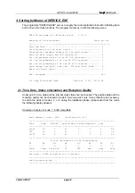
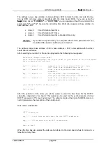
Страница 8: ...te radio bit DCF sim Eval Mode 8 Reset the radio board 9 Exit programm Esc c hopf Elektronik GmbH Version 3 00 18 12 98 4 1 Time Date Status Information and Reception Quality Under point 1 time date and the internal clock status can be checked The position data and the reception quality can be checked in mode 2 in menu point 4 only It may therefore be necessary to switch the clock to mode 2 3 or 4...

Страница 9: ...r is transmitted The time evaluation can also be done in the position fixed mode which requires only one satellite for synchronisation see chapter 0 The entry Max Sat states the number of visible satellites Six satellites can be received The entry Sat No S N states the satellite pseudo random number The satellites are not numbered 1 2 3 etc but named after the pseudo random number of the satellite...

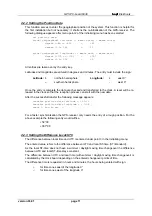
Страница 10: ... 1 Set position data 2 Set difference time UTC Local 3 Set change over daylight saving and standard time 4 Set time out DCF77 simulation and sync bit 5 Set Evaluation Mode 3 D Position fix 6 Back to the main menu Esc after pressing the according key the data can be entered and transferred to the clock 4 2 1 Setting Time and Date This menu point is used to set the valid time information The calcula...

Страница 11: ...be re leased in the clock so that the reception process can start with the new data After the successful transfer the following message appears transfer position data latitude 51 12 transfer position data longitude 7 34 ready end by key For a faster synchronisation the GPS receiver only needs the entry of a rough position For the above example the following entry would suffice 50 00 007 00 4 2 3 S...

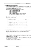
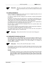
Страница 12: ...calculated automatically for the subsequent years The entered values can be checked under menu item 8 of the main menu view points of changeover radio bit DCF77 sim evaluation mode Please note Minute entries other than 0 do not result in correct changeovers 4 2 5 Setting DCF77 Simulation and Sync bit This function under pt 5 of the initialising menu can be used to delay the changeover of the statu...

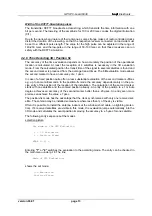
Страница 13: ... have an accuracy of 1 µsec In case of a fixed position quite often a less substantial evaluation of the second marker suffices e g up to some milliseconds In the position fix mode the accuracy depends mainly on the pre cise entry of the position of the location of the installation The calculation of the second marker starts with one satellite and the entered position already An entry of the posit...

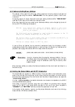
Страница 14: ...alid and does not transfer any addresses but plausible ones ranging from 200 to 1FC0 in steps of 40 into the clock example 200 240 280 2C0 300 1F00 1F40 1F80 1FC0 Please note A reset is necessary after changing the hardware address The serv ice software have to be started again The programme does not check the new address range for addresses which may be used by other adapter boards When the base ...

Страница 15: ... output mode First read the paragraph set output mode in your manual of the clock board before changing the settings key 1 mode 1 compatible with clock board 6036 local time UTC local time standard time only key 2 mode 2 local time with position data and status in formation key 3 mode 3 UTC Universal Time Coordinated with position data and status information key 4 mode 4 Local Time standard time o...

Страница 16: ... week 07 date 23 10 96 active time out radio bit after 2 minutes time out DCF77 simulation after 2 minutes DCF77 simulation length of Hi Bit 200 milliseconds DCF77 simulation length of Lo Bit 100 milliseconds You must wait at least one minute until the new change over points have been calculated by the radio controlled clock press any key here you can control the change over date and it s status A...

Страница 17: ...ength 1 second hour pulse length 1 second 24 h pulse length 1 second the signals are delivered in TTL Level active low Connection diagram See appendix 7 Files on the Disc The supplied system disc for the clock board contains the following files DOS_DRV Funkinst exe DOS synchronisation process WIN31x Hopftime exe Windows 3 x synchronisation process WIN95 SyncProc exe Windows 95 98 synchronisation p...

Страница 18: ...ing protection is broken example 2 7 satellites are within the view range but only up to 2 appear on display Possible errors the view range of the antenna to the sky is too small example 3 9 satellites appear in the view range 6 are recorded but the system does not synchronise be cause the signal noise ratios are all between 10 25 Possible causes the cable is too long the BNC connectors are badly ...

Страница 19: ... there is a possible address conflict with other hardware if the contact surfaces of the board are soiled If the computer bios setup allows the choice to run the ISA bus either synchronously or asyn chronously the bus must be switched explicitly to asynchronous mode The IOCHRDY signal is needed for an error free data transmission 9 Delivery Condition The clock board 6038 is delivered with the foll...

Страница 20: ...d BNC antenna connector LED crystal radio operation SUB D connector 9 pole pin allocation pin allocation 1 day pulse 6 DCF77 pulse out 2 hour pulse 7 RS232 RxD 3 minute pulse 8 RS232 TxD 4 second pulse 9 1 kHz 5 GND Please note The standard interface cable can t be used while employing the serial interface ...

Страница 21: ...first installation without position data warm start ca 2 min voltage failure 3 days accuracy of the PPS pulse 1 microsecond 95 temperature range 0 60 C Technical Data Antenna type of antenna micro strip antenna mid frequency 1 575 42 MHz band width 10 MHz antenna amplifier voltage supply 5 V DC 0 5 V via antenna cable impedance 50 Ohm power amplifier 20 dB length of cable max 25 m with hopf hopf_ ...

Страница 22: ...GPS PC board 6038 hopf hopf Elektronik version 03 01 page 22 ...

Отзывы: