SPYDER MODEL 5 ENGINEERING TOOL
–
USER GUIDE
31-00282ES-01
60
IRM Function Blocks and External Application Components
The IRM program accepts IRM control components only. Direct connection between IRM control function blocks with
Niagara components by using the Niagara Link function does not work. External communication should be established
via BACnet components which link the IRM function blocks to the Niagara components.
Application Templates Usage
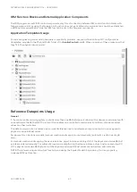
For quick engineering and avoiding hardware compatibility problems, use pre-defined onboard I/O configurations
(templates) provided in the
PhysicalPoints
folder of the
honIrmControl
palette. When using any of these, make sure that
they fit to the physical device model.
Reference Datapoints Usage
General
If the control and monitoring system contains more than one BACnet device (controller), the devices communicate with
one another via the BACnet MSTP protocol. This enables one controller to read values from other controllers and set
values on other controllers.
This data communication is realized via so-called reference input and reference output points which are assigned to
physical or value BACnet points.
Assignments can be done manually (manual creation and mapping) or automatically (automatic creation via drag &
drop).
For manual creation and mapping, the device instance, object instance and object ID of the physical and value BACnet
points are entered manually. For automatic creation via drag & drop, the device instance, object instance and object ID
of the physical and value BACnet points of the physical and value BACnet points are carried over automatically.
NOTE: The reference input and output function provided by the Spyder Model 5 Engineering Tool is a proprietary
Honeywell BACnet function.

