background image

ID61/62 Series Panel - Operating Manual

Operator 

Actions at Panel

46

997-458-000-8, Issue 8
January 2010

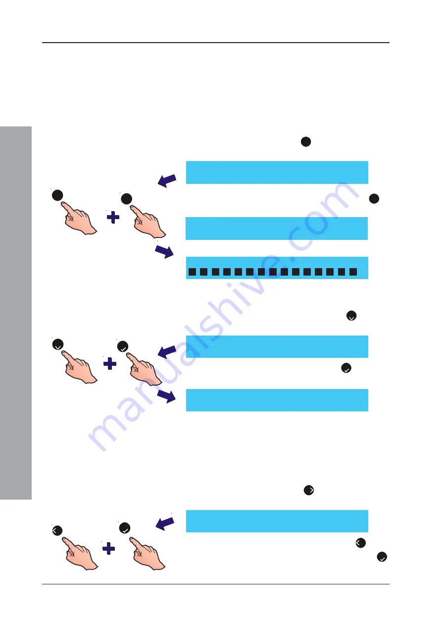
4.14.3 Print On-Demand

This option is only available if the panel was configured
for ‘On-Demand’ printing during commissioning.

Note:

If On-Demand is 

not

 configured, events are printed

as they occur. If On-Demand 

is

 configured, events

are only printed via the menu as described below.

To 

print

 On-Demand (if configured), proceed as follows:

1

At the Print menu, press ‘

3

’ on the numeric keypad

to select the On-Demand option.

2

To print, at the Print On Demand menu press ‘

1

’ to

select Start.

3

Events stored since the last print are sent to the printer.

To 

purge

 the stored events (i.e. to prevent them being

printed):

1

At the Print On Demand menu, press ‘

2

’ to select

Purge.

2

At the confirmation message, press ‘

5

’ to confirm

that the events are to be deleted.

4.14.4 Print Continuous - Purge

If the printing mode was configured as ‘Continuous’ during
commissioning, it is still possible to purge the stored
events 

during

 printing. This menu option is only available

when the printer is ‘active’, i.e. it is in the process of
printing. Select the Print option from the Access level 2
user menu by pressing the ‘

6

’ button. The following

print menu is displayed:

To purge the current print session, press the 

4

 button

and then, at the confirmation message, press the ‘

5

pushbutton to confirm.

Purge Pending Event Log Prints
Press 

to Confirm

<:Cancel

2

3

[U0 PRINT ON DEMAND]

1 : Start

2 : Purge

1

On Demand Printing In Progress

<: Stop

[U0 PRINT ON DEMAND]

1 : Start

2 : Purge

5

[U0 PRINT]

1 : Log

2 : Disablements
4 : Purge

4

5

[U0 PRINT]

1 : Log

2 : Disablements

3 : On-Demand

4 : Maintenance

Содержание NOTIFIER ID61

Страница 1: ...ID61 62 operating manual 997 458 000 8 Issue 8 January 2010 ...

Страница 2: ...arm 11 3 5 Fault Output Fault Disabled Optional 11 4 Operator Actions at Panel 12 4 1 Introduction 12 4 1 1 Liquid Crystal Display 12 4 1 2 Internal Buzzer 13 4 1 3 Access Codes 13 4 1 4 Keyswitch 14 4 2 MUTE BUZZER Pushbutton 14 4 3 EXTEND DELAY Pushbutton 14 4 4 END DELAY EVACUATE Pushbutton 15 4 5 SILENCE RESOUND Pushbutton 16 4 6 RESET Pushbutton 17 4 7 Numeric Keys 18 4 7 1 Cancellation Termi...

Страница 3: ...4 11 2 Date User Option 36 4 12 VIEW MODE User Option 37 4 12 1 Log User Option 38 4 12 2 Devices User Option 39 4 12 3 Faults User Option 40 4 12 4 Input Events User Option 41 4 12 5 Disabled User Option 42 4 12 6 Alarm Count User Option 42 4 12 7 Voltages User Option 43 4 12 8 Version User Option 44 4 13 Commissioning 44 4 14 PRINT User Option 44 4 14 1 Print Log 45 4 14 2 Print Disablements 45 ...

Страница 4: ...ILENCE RESOUND END DELAY EVACUATE END DELAY EVACUATE 4 6 0 0 9 3 1 1 7 5 9 8 4 2 2 3 4 5 6 7 8 9 10 11 12 13 14 15 16 ZONE FIRE ZONE FIRE ZONE FAULT DISABLE TEST ZONE FAULT DISABLE TEST FIRE DISABLEMENT FAULT TEST POWER SUPPLY FAULT EARTH FAULT POWER PLANT ALARM FIRE OUTPUT ACTIVE DELAYS ACTIVE FIRE OUTPUT FAULT DISABLED FIRE CONTROL O P FAULT DISABLED PRE ALARM SYSTEM FAULT SOUNDER FAULT DISABLED...

Страница 5: ... 62 Series Panel Installation CommissioningandConfiguration Manual Ref 997 457 000 X 1 2 The ID61 62 Panels The panel as supplied by NOTIFIER is a 1 loop 16 zone Analogue Addressable Panel The single loop has the capacity for up to 99 analogue sensors plus up to 99 modules and in some installations panels may also be connected to repeaters using the RS485 Communications Link The panel can also sup...

Страница 6: ... not supported in UK ESM Extinguishant System ESO Monitored Extinguishing System Output EST Extinguishant Monitor System Trigger ION Ionisation Smoke Detector IRL Immediate Release Input LBM Loop Booster Module MCP Manual Call Point MLT Advanced Multi Sensor MNS Monitor module no short circuit MON Fire Alarm Monitor Input MRL Manual Release Input M CZ Conventional Interface input OPAL OPT Optical ...

Страница 7: ...ATE Section 4 6 1 Also configurable as Transmission Device TD Enable Disable Numeric Cursor Keys Numeric Cursor keys Section 4 6 Keyswitch Turn the keyswitch to enable level 2 access The keyswitch provides an alternative to entering the level 2 access code via the numeric keys See Section 4 1 3 and Section 4 1 4 EXTEND DELAY END DELAY EVACUATE SILENCE RESOUND RESET MUTE BUZZER FIRE RESET MUTE BUZZ...

Страница 8: ...a pre alarm condition exists POWER indicates status of power supply SYSTEM FAULT indicates the CPU has reset or a system fault has occurred EARTH FAULT indicates an earth fault has occurred PLANT ALARM2 indicates a fault or warning from a plant monitoring device FIRE CONTROL O P FAULT DISABLED indicates a fire control output fault or disablement FIRE OUTPUT FAULT DISABLED indicates a fire output f...

Страница 9: ...m detects a fire alarm the panel always does the following automatically a Operates the internal high pitched buzzer b Illuminates the red FIRE LEDs and the numbered red ZONE FIRE LED c Displays information on the LCD regarding the fire condition The information includes device address and device locaion see example below Note If a delay is configured DELAYED is displayed on the top line of the LC...

Страница 10: ...ent it is possible to manually scroll through all logged Fire Alarm conditions using the 2 8 arrows 5 When evacuation of the premises is achieved or at the direction of an authorised person the Alarm Sounders may be silenced by pressing the SILENCE RESOUND pushbutton Note The SOUNDERS SILENCED LED illuminates if this option was configured during panel commissioning The default function for this LE...

Страница 11: ...ushbutton The LCD displays the alarm information on the top line this alternates for 1 sec every 5 secs with the time remaining before the shortest day mode delay expires 1b If the 2 stage delay is configured pressing the EXTEND DELAY pushbutton during the primary delay initiates the fire investigation period Note If configured to do so the DISABLEMENT LED is illuminated not default from the initi...

Страница 12: ...information on the LCD regarding the pre alarm condition d Operation of any assigned outputs in response to a general pre alarm condition at the panel refer to Section 5 7 Control by Event Rules Recommended operator actions 1 Operate the MUTE buzzer pushbutton to silence the panel s internal buzzer 2 Check condition of sensor indicated and check area for possible fire If the cause cannot be determ...

Страница 13: ...me fault was logged Depending upon the fault message either i If the fault message relates to a specific loop device investigate whether the cause of the fault is immediately apparent and can be corrected FAULT 01 03 14 55 EARTH FAULT A H B C D FAULT 01 03 Z01 M12 MCP 14 55 NO REPLY FROM DEVICE A H E G F D B C FAULT 01 03 Z01 M12 MCP 14 55 Zone Text Device Text Note Press the 6 button to view addi...

Страница 14: ...ber of faults logged d Time fault was logged e A text message describing the fault A battery fault is shown on the LCD as follows 2 If a service contact number has been configured the LCD alternates between the power fault message and the service contact number Note Press the MUTE BUZZER pushbutton to silence the panel s internal buzzer 3 When the cause of the fault has been cleared press the RESE...

Страница 15: ... alarms d Zone number e Device address f Device type g Time of logged message h Zonal and device text if any When the cause of the alarm has been cleared the message will automatically be removed from the LCD and the LED extinguished The panel returns to quiescent mode 3 5 Fault Output Fault Disabled Optional If the panel has been configured to indicate the status of the Fault Output relay circuit...

Страница 16: ...ccess code see Section 4 1 3 Access Codes 4 1 1 Liquid Crystal Display The Liquid Crystal Display LCD provides 80 characters of alphanumeric information on a 2 line display The LCD is backlit to assist viewing under dim ambient light conditions System Normal Display When in a quiescent state the LCD shows the Status NORMAL message on line 1 and the day date and time on line 2 The message will be d...

Страница 17: ...el 3 S1 is displayed in place of the user identification number 1 Press the button at the Status NORMAL message to prompt for a Level 2 3 access code as shown below 2 Press and hold the 0 9 button while pressing the appropriate 4 digit Level 2 access code will appear on the LCD as the numbers are entered 3 Press the 5 button to confirm the entered code The Level 2 Options are then displayed 4 The ...

Страница 18: ...ZZER pushbutton when an alarm or fault has occurred silences the internal buzzer If the Primary Delay is active during an alarm condition this pushbutton will also terminate this delay and start the Extend Delay time The internal buzzer remains silent until the system is RESET or the panel detects another alarm condition 4 3 EXTEND DELAY Pushbutton With the occurrence of an alarm and with the Prim...

Страница 19: ...Y EVACUATE pushbutton The following is typically displayed 2 No further action is needed until it is required to silence the sounders in which case the SILENCE RESOUND pushbutton should be pressed see Section 4 5 Silence Resound pushbutton Note If the pushbuttons are enabled to operate at Level 2 enter the Level 2 passcode in the manner described in the RESET pushbutton procedure Section 4 6 No Al...

Страница 20: ...ays are active proceed as follows 1 Press the SILENCE RESOUND pushbutton The following are not switched off by this operation a The internal FIRE buzzer b Any output modules configured in the CBE Rules during commissioning NOT to be silenced by the SILENCE RESOUND pushbutton 2 To start the sounders again in the same pattern as they were previously operating and reactivate any programmed delays pre...

Страница 21: ...or Level 1 operation the following occurs a All FIRE and FAULT lamps are switched off b All sounders cease to operate c The system status returns to NORMAL provided that no operator actions are being carried out If the pushbuttons are enabled to operate at Level 2 follow the procedure below 1 Press the RESET pushbutton The LCD displays the following 2 Either turn the keyswitch or enter an appropri...

Страница 22: ... available b Press the 5 button to confirm an option c Press the 0 9 Shift button to enable number entry Following the input of a number approx 1 second later a second audible bleep indicates that number entry is no longer enabled d When an internal printer is fitted press the un shifted 0 button to feed the printer paper one press of the 0 button advances the paper by one line 4 7 1 Cancellation ...

Страница 23: ... a printer is fitted The menu map at left shows an overview of the Level 2 menus The Commissioning menu is shown inverted to indicate that a Level 3 access is required Notes 1 Level 3 Configuration Menus are described in 997 457 000 X ID61 62 Series Panel Installation Commissioning Configuration Manual Section 5 Configuration 2 With a fire alarm active the panel status display will override the us...

Страница 24: ...el 2 access code and confirm using the 5 button The User Option menu is displayed with the user number U0 to U9 in the top left hand corner Note Print menu option displayed only when a printer is fitted Extinguishing System Testing SLC device outputs To prevent inadvertant operation of the direction and release valves during testing zones containing the associated SLC devices MUST FIRST be put int...

Страница 25: ...racter in turn To test the LCD enter access Level 2 and follow the procedure below 1 Using the numeric keypad press 1 to display the TEST menu 2 To test the LCD press the 2 button on the numeric keypad 3 Each character is then displayed in turn on the LCD When all characters have been displayed press the 4 button to cancel and return to the Test Menu U0 1 Test 2 Disable Enable 3 Clock 4 View Mode ...

Страница 26: ...ed Test the devices see Checking the Devices overleaf iii Press the 4 button to exit the Ring Sounders menu and return to the Zones menu b To walk test devices on a specific zone without activating the sounder press 2 on the numeric keypad to select the No Sounders option The walk test procedure is otherwise the same as given above for Ring Sounders 3 To end the walk test a For a specified zone at...

Страница 27: ...s by applying smoke or heat as appropriate or by operating the device s internal test switch by means of a magnet ii Test Manual Call Points by using a test key For each device the panel will record the event in the log sound its internal buzzer illuminate the appropriate ZONE LED and turn on the LED at the device that initiated the alarm For OPAL protocol devices the longer green LED flash durati...

Страница 28: ...Test Menu using the numeric keypad press the 4 button to select the Auto High Test 2 When the LCD displays the start Auto High Test message press the 5 button to start the test 3 Each sensor is tested individually The device under test is displayed on line 2 of the LCD in the format shown below then re displays the Test Menu 4 After each device test the pass or fail message is displayed as in the ...

Страница 29: ...ng 4 Check that the output operates To stop the test press the 4 button Press the 4 button again to return to the Test Outputs menu Test SLC Outputs 1 From the Outputs menu press the 2 button on the numeric keypad to display the SLC Output Test menu 2 Use the 2 8 buttons to select the output required for testing and press the 5 button to start the test The LCD then displays the following 3 Check t...

Страница 30: ... prompting for entry of access level 3 passcode 2 Having entered the access level 3 passcode press the 5 button to start the test 3 Before the test starts a 0 percentage indication of the equipmentundertestisdisplayedonthetopline Asthetest progresses the percentage value increases to 100 to indicatethatallloop powereddevicesundertestareoperating correctly This percentage value may go down if a dev...

Страница 31: ...options To test the keyboard press the 7 button on the numeric keypad 3 The following screen is displayed Press each panel pushbutton in turn When a pushbutton is pressed the corresponding display entry is replaced by an equivalent number of asterisk characters The five pushbuttons are represented by A to E A being the top button Once all pushbuttons have been pressed the display will return to th...

Страница 32: ...de 2 Either turn the keyswitch or using the numeric keypad enter the correct Level 2 access code and confirm using the 5 button to display the menu The LCD displays the user number U0 to U9 in the top left hand corner Note An incorrect access code causes the LCD to display the ERROR INCORRECT PASSCODE message After one minute the LCD returns to the Status NORMAL message 3 Using the numeric keypad ...

Страница 33: ...ll Zone or Devices in zone Note Press the 2 8 pushbuttons to step to the previous nextzoneandconfirmusingthe 5 button 4 To disable a A Full Zone Press the 1 pushbutton on the numeric keypad to select the Full Zone option and the 5 pushbutton to confirm The DISABLEMENT and relevant ZONE FAULT DISABLE TEST LED s illuminate indicating that the selected zone s are now disabled The LCD returns to the D...

Страница 34: ... enabled The DISABLEMENT LED remains illuminated if one or more devices are disabled It is extinguished when all devices have been enabled The relevant ZONE FAULT DISABLE TEST LED is illuminated when ALL devices in that zone have been disabled the ZONE FAULT DISABLE TEST LED is NOT lit with partial disablements Disablement ofALL devices is confirmed by the Fully Disabled LCD message 6 Press the 4 ...

Страница 35: ... c Press the 2 button to disable enable all Extinguishant System outputs d Press the 3 button to disable enable all Fault relay outputs e Press the 5 button to disable enable other relays and control outputs 3 Press the 5 button to confirm the selected operation The LCD automatically returns to the Disable Enable menu When outputs are disabled the general DISABLEMENT LEDand ifapplicable theFIRECON...

Страница 36: ... illuminates when Day Mode is started 3 To end Day Mode repeat steps 1 and 2 the display is as shown below The DELAYACTIVE LED will extinguish when the Day Mode operation has been ended either when day mode is turned off or when the timer has timed out No delays are active Note If Day Mode is NOT cancelled manually Day Mode delays are automatically deactivated at the end of the set time period U0 ...

Страница 37: ...en the delays are disabled the DELAY ACTIVE LED is extinguished When the delays are enabled the LED is illuminated If a Day Mode time period is configured the CBE Rule delays will activate when Day Mode is started either a Using the Disable Enable menu or b When Digital ÜE Input 1 is operated if this input is configured during commissioning for Day Mode Start These delays will be deactivated when ...

Страница 38: ...cesscodeisentered theLCDdisplays an ERROR INCORRECT PASSCODE After one minute the LCD returns to the Status NORMAL message 2 Either turn the keyswitch or using the numeric keypad enter the correct Level 2 3 access code and confirm using the 5 button The Level 2 menu is displayed with the user number U0 to U9 in the top left hand corner 3 Press the 3 button on the numeric keypad to select the Clock...

Страница 39: ... numbers directly All digits are automatically entered into position from left to right on the display After entering the last digit press the 5 button to confirm and return to the CLOCK menu Note The entered time must be in the 24 hour clock format e g for 07 11 pm enter 1911 If an invalid time is entered the LCD displays an error message and then re displays the Clock menu U0 Clock 1 Time 2 Date...

Страница 40: ...cally entered into position from left to right on the display After entering the last digit press the 5 button to confirm and return to the Clock menu Note The date MUST be entered in the same format as indicated on the LCD Only date entries between 2000 and 2063 are valid If an invalid date is entered for example 222222 22 22 22 the LCD displays an error message and then re displays the Clock men...

Страница 41: ...correct access code is entered the LCD displays an ERROR INCORRECT PASSCODE After one minute the LCD returns to the Status NORMAL message 2 Either turn the keyswitch or using the numeric keypad enter the correct Level 2 access code and confirm using the 5 button The Level 2 menu is displayed with the user number U0 to U9 in the top left hand corner 3 Using the numeric keypad press the 4 button to ...

Страница 42: ...m this point press the 2 8 buttons to scroll through the Log entries Example Log entries are given below Note Press the 6 button to view additional zone text information To return to the previous display press any numeric cursor key Alternatively if no key is pressed within ten 10 seconds the LCD returns to the View Log display automatically 3 Press the 4 button to return to the View Mode menu U0 ...

Страница 43: ...050 U0 Sensor nn AAA Next More PW1 286 2 283 3 285 4 1003 5 0292 Exit CLIP protocol OPAL protocol Device Type Device Address U0 Sensor 02 OPT Next More PW1 286 2 283 3 285 4 1003 5 0292 Exit U0 Sensor 03 OPT Next More PW1 286 2 283 3 285 4 1003 5 0292 Exit Device Type Device Address Pulse Width Time Periods 2 8 3 Press the 6 button to view additional device information For CLIP protocol devices No...

Страница 44: ...isplay reverts to the fault message Example fault displays are given below a Fault condition b Fault currently displayed c Total number of faults logged d Text description of fault e Zone Number f Device Address g Device Type h Time fault was logged Note If no faults are recorded on the system the following message is displayed 3 Press the 4 button to return to the View Mode menu U0 View 1 Log 2 D...

Страница 45: ...input events recorded on the system 3 If a number of input events are present press the 2 8 buttons to scroll through the entries a Plant Alarm condition b Alarm currently displayed c Number of alarms d Zone Number e Device Address f Device Type g Time alarm was logged h Zonal and Device text if any Note Plant alarms for Hold Switch and Abort Switch inputs are entered as AUX events in the Fault li...

Страница 46: ...splayed c Active disablements d Zone number e Device address f Device type g Zonal and device text if any 4 Press the 4 button to return to the View Mode menu 4 12 6 Alarm Count User Option TheAlarm Count User Option allows the user to view the number of times the panel has entered alarm condition since manufacture To view the Alarm Count from the VIEW Mode menu 1 Using the numeric keypad press th...

Страница 47: ...s too low The values are for service engineer use only d A mains failure is detected when the AC voltage drops below 193Vac This fault will remain until the AC voltage rises above 205Vac e The Charger is faulty if a value less than 24V is displayed 3 Press the 4 button to cancel and return to the View Mode menu U0 View 6 Maint 7 Alarm Count 8 Voltages 9 Version More U0 VOLTS BATTERY VOLTS 27 0 Sel...

Страница 48: ...ssioning Configuration Manual Sections 4 and 5 4 14 PRINT User Option The print options available are as follows a Internal printer b External printer terminal or PC via the RS232 port Themenuoptionsareavailabletoeitherprinterconfiguration However in instances where an internal printer is fitted and connection to external equipment is also required the menu options only apply to the internal print...

Страница 49: ...lected range is then sent to the printer Note If the paper runs our while printing is in progress abort the current print session before changing the paper roll and then re select the print option 4 14 2 Print Disablements This option prints current disablements for previous logged disablements use the Log option described above Proceed as follows 1 At the Print menu press 2 on the numeric keypad ...

Страница 50: ...e Print On Demand menu press 2 to select Purge 2 At the confirmation message press 5 to confirm that the events are to be deleted 4 14 4 Print Continuous Purge If the printing mode was configured as Continuous during commissioning it is still possible to purge the stored events during printing This menu option is only available when the printer is active i e it is in the process of printing Select...

Страница 51: ...sors 1 At the Print menu press 4 on the numeric keypad to print the maintenance log The display changes to indicate that printing is in progress as below Note The Maintenance log can hold up to 100 log entries Newer entries replace the oldest in the log 2 Press the 4 button to cancel printing and return to the Print menu Printing Maintenance Log 4 U0 PRINT 1 Log 2 Disablements 3 On Demand 4 Mainte...

Страница 52: ...person should be recorded All events should be properly recorded events include real and false fire alarms faults pre alarm warnings tests temporary disconnections and service visits Abrief note of any work carried out or outstanding should be made Sample pages of the log book are provided here and can be photocopied to produce a log book that conforms to EN54 14 The sample below is for the refere...

Страница 53: ...ID51 52 Series Panel Operating Manual Appendix 1 Log Book A1 2 997 458 000 8 Issue 8 January 2010 Date Time Event Action Required Date Completed Initials Event Data ...

Страница 54: ...ID51 52 Series Panel Operating Manual Appendix 1 Log Book A1 3 997 458 000 8 Issue 8 January 2010 Date Time Event Action Required Date Completed Initials Event Data ...

Страница 55: ...ID51 52 Series Panel Operating Manual Appendix 1 Log Book A1 4 997 458 000 8 Issue 8 January 2010 Date Time Event Action Required Date Completed Initials Event Data ...

Страница 56: ...ecord of the device and zone tested each week Record and report any malfunction Quarterly The responsible person should ensure that every three months the system is checked by a competent person who shall Check the log book entries and any action taken Check the standby batteries and the charger voltage Test at least one device in each zone to check the panel functions Check the operation of the a...

Страница 57: ...not be exposed to smoke or any other abnormal conditions otherwise the panel may report a sensor fault SMART 4 Sensor No user procedures are required with this sensor However a new advisory message is logged whenever a SMART 4 device approaches the end of the useful life of the CO sensor element approximately 6 months before the sensor needs a complete replacement A new print option is available w...

Страница 58: ...tion therein Design features may be changed or amended without prior notice Quality Systems Certificate No 154 Assessed to ISO9001 L O S S P R E V E N T ION CERTIFI C A T I O N B O A R D 007 Charles Avenue Burgess Hill W Sussex RH15 9UF T 44 0 1444 230 300 F 44 0 1444 230 888 E sales notifierfiresystems co uk www notifierfiresystems co uk ...

Отзывы: