


COMPONENT MAINTENANCE MANUAL
00001059
CAUTION: HOLD STRONGLY THE EQUIPPED HOUSING DURING THE INSTALLATION OF
THE ROTOR.
(f)
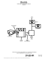
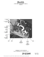
Install the rotor (01-630) in the equipped housing (01-640) with the rotor installation
guide (T05).
(g)
Apply a layer of adhesive material (M38B) on the threaded part of the screws (01-570).
CAUTION: BEFORE THE INSTALLATION OF THE OUTER REAR FLANGE (01-560), CHECK
IF THE THREE HOLES FOR THE TIE RODS (01-440) ARE OPENED UP TO THE
STATOR SIDE, THIS WILL AFFECT THE INSTALLATION OF THE TIE RODS
(01-440) (REF. SUBTASK 21-22-91-410-002-A01).
(h)
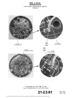
Put the outer rear flange (01-560) in position against the rear bearing.
NOTE:
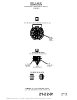
Refer to Fig. 7001 detail A for the orientation of the outer rear flange (01-560).
(i)
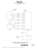
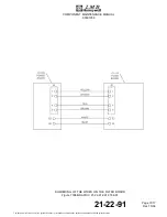
Put the stator wires through the dedicated ports of the outer rear flange (01-560).
(j)
Attach the outer rear flange (01-560) with the four screws (01-570).
(k)
Torque the screws (01-570) to the specified value (Ref. TASK 21-22-91-820-802-A01)
(l)
Install the outer front flange (01-550) and the retaining ring (01-540).
NOTE:
Make sure that the rotor (01-630) turns freely.
(m)
Install the six spring washers (01-530) against the rear bearing (01-620) (Ref. Fig.
7001 detail B).
(n)
Install the inner rear flange (01-550) and the retaining ring (01-540).
(o)
Apply a layer of adhesive material (M38B) on the threaded part of the screws (01-610).
(p)
Attach the inner front flange (01-600) with the three screws (01-610) and the three
washers (01-620).
NOTE:
Put a long M3 screw or an M3 threaded rod in one hole of the inner front flange
(01-600) to pull it close to the equipped housing (01-640).
(q)
Torque the screws (01-610) to the specified value (Ref. TASK 21-22-91-820-802-A01)
(r)
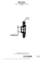
Do a check of the pressure of the spring washers (01-530).
– Put the comparator sensor against the inner rear flange (01-520).
– Apply a pressure of 2,50 ± 0,20 kg to the inner rear flange (01-520).
– Make sure that the inner rear flange (01-520) starts moving at this value.
– If necessary, add one more spring washer (01-530) as shown on detail B (Ref. Fig.
21-22-91
Page 7003
Dec 15/06
The document reference is online, please check the correspondence between the online documentation and the printed version.