


COMPONENT MAINTENANCE MANUAL
00001059
(c)
Supply the fan under 28 VDC.
(d)
On the test lead (T01), set the power switch to the ON position.
(e)
Make sure that the fan starts.
(f)
On the test lead (T01), set the power switch to the OFF position.
(g)
Make sure that the fan stops.
(h)
Remove the fan from the test bench (T02).
(i)
Disconnect the test lead (T01) from the fan.
SUBTASK 21-22-91-750-003-A01
(3)
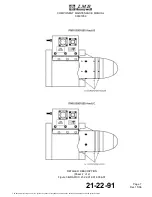
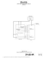
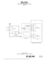
High Speed & Low Speed Selection Test
(Ref. Fig. 1002)
(a)
Attach the fan on the test bench (T02).
(b)
Connect the fan to the test lead (T01).
(c)
Supply the fan under 28 VDC.
(d)
On the test lead (T01), set the power switch to the ON position.
(e)
On the test lead (T01), set the speed selection switch to the low speed position.
(f)
Make sure that the fan operates at low speed.
(g)
On the test lead (T01), set the speed selection switch to the high speed position.
(h)
Make sure that the fan operates at high speed.
(i)
Remove the fan from the test bench (T02).
(j)
Disconnect the test lead (T01) from the fan.
SUBTASK 21-22-91-750-004-A01
(4)
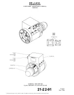
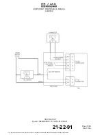
Start-up Current Test
(Ref. Fig. 1003)
(a)
Attach the fan on the test bench (T02).
(b)
Connect the fan to the test lead (T01).
(c)
Supply the fan under 28 VDC.
(d)
On the test lead (T01), set the power switch to the ON position.
(e)
At start-up, check the input current curve with an oscilloscope. Record the value.
(f)
Make sure that the input current value is less than 40 A during the first 1,2 s.
(g)
Remove the fan from the test bench (T02).
21-22-91
Page 1003
Dec 15/06
The document reference is online, please check the correspondence between the online documentation and the printed version.