


Rev. 2.10
2�0
���� 02� 201�
Rev. 2.10
2�1
���� 02� 201�
HT68F20/HT68F30/HT68F40/HT68F50/HT68F60
HT68FU30/HT68FU40/HT68FU50/HT68FU60
Enhanced I/O Flash Type 8-Bit MCU with EEPROM
HT68F20/HT68F30/HT68F40/HT68F50/HT68F60
HT68FU30/HT68FU40/HT68FU50/HT68FU60
Enhanced I/O Flash Type 8-Bit MCU with EEPROM
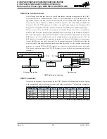
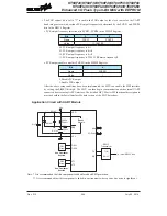
UART Module Interrupt Structure
Several individual UART conditions can generate a UART interrupt. When these conditions exist,
a low pulse will be generated on the INT line to get the attention of the microcontroller. These
conditions are a transmitter data register empty, transmitter idle, receiver data available, receiver
overrun, address detect and an RX pin wake-up. When any of these conditions are created, if its
corresponding interrupt control is enabled and the stack is not full, the program will jump to its
corresponding interrupt vector where it can be serviced before returning to the main program. Four
of these conditions have the corresponding USR register flags which will generate a UART interrupt
if its associated interrupt enable control bit in the UCR2 register is set. The two transmitter interrupt
conditions have their own corresponding enable control bits, while the two receiver interrupt
conditions have a shared enable control bit. These enable bits can be used to mask out individual
UART interrupt sources.
The address detect condition, which is also a UART interrupt source, does not have an associated
flag, but will generate a UART interrupt when an address detect condition occurs if its function
is enabled by setting the ADDEN bit in the UCR2 register. An RX pin wake-up, which is also a
UART interrupt source, does not have an associated flag, but will generate a UART interrupt if
the microcontroller is woken up by a falling edge on the RX pin, if the WAKE and RIE bits in the
UCR2 register are set. Note that in the event of an RX wake-up interrupt occurring, there will be a
certain period of delay, commonly known as the System Start-up Time, for the oscillator to restart
and stabilize before the system resumes normal operation.
Note that the USR register flags are read only and cannot be cleared or set by the application
program, neither will they be cleared when the program jumps to the corresponding interrupt
servicing routine, as is the case for some of the other interrupts. The flags will be cleared
automatically when certain actions are taken by the UART, the details of which are given in the
UART register section. The overall UART interrupt can be disabled or enabled by the related
interrupt enable control bits in the interrupt control registers of the microcontroller to decide whether
the interrupt requested by the UART module is masked out or allowed.
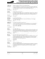
UART Interrupt Structure


