


Rev. 2.10
230
���� 02� 201�
Rev. 2.10
231
���� 02� 201�
HT68F20/HT68F30/HT68F40/HT68F50/HT68F60
HT68FU30/HT68FU40/HT68FU50/HT68FU60
Enhanced I/O Flash Type 8-Bit MCU with EEPROM
HT68F20/HT68F30/HT68F40/HT68F50/HT68F60
HT68FU30/HT68FU40/HT68FU50/HT68FU60
Enhanced I/O Flash Type 8-Bit MCU with EEPROM
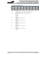
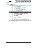
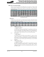
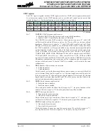
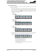
UCR1 register
The UCR1 register together with the UCR2 register are the two UART control registers that are used
to set the various options for the UART function such as overall on/off control, parity control, data
transfer bit length, etc. Further explanation on each of the bits is given below:
Bit
7
6
5
4
3
2
1
0
Name
UARTEN
BNO
PREN
PRT
STOPS
TXBRK
RX8
TX8
R/W
R/W
R/W
R/W
R/W
R/W
R/W
R
W
POR
0
0
0
0
0
0
×
0
"x" �nknown
Bit 7
UARTEN
: UART function enable control
0: Disable UART. TX and RX pins are in the state of high impedance
1: Enable UART. TX and RX pins function as UART pins
The UARTEN bit is the UART enable bit. When this bit is equal to "0", the UART
will be disabled and the RX pin as well as the TX pin will be in the state of high
impedance. When the bit is equal to "1", the UART will be enabled and the TX and
RX pins will function as defined by the TXEN and RXEN enable control bits. When
the UART is disabled, it will empty the buffer so any character remaining in the buffer
will be discarded. In addition, the value of the baud rate counter will be reset. If the
UART is disabled, all error and status flags will be reset. Also the TXEN, RXEN,
TXBRK, RXIF, OERR, FERR, PERR and NF bits will be cleared, while the TIDLE,
TXIF and RIDLE bits will be set. Other control bits in UCR1, UCR2 and BRG
registers will remain unaffected. If the UART is active and the UARTEN bit is cleared,
all pending transmissions and receptions will be terminated and the module will
be reset as defined above. When the UART is re-enabled, it will restart in the same
configuration.
Bit 6
BNO
: Number of data transfer bits selection
0: 8-bit data transfer
1: 9-bit data transfer
This bit is used to select the data length format, which can have a choice of either 8-bit
or 9-bit format. When this bit is equal to 1, a 9-bit data length format will be selected.
If the bit is equal to "0", then an 8-bit data length format will be selected. If 9-bit data
length format is selected, then bits RX8 and TX8 will be used to store the 9th bit of the
received and transmitted data respectively.
Bit 5
PREN
: Parity function enable control
0: Parity function is disabled
1: Parity function is enabled
This is the parity enable bit. When this bit is equal to "1", the parity function will be
enabled. If the bit is equal to "0", then the parity function will be disabled.
Bit 4
PRT
: Parity type selection bit
0: Even parity for parity generator
1: Odd parity for parity generator
This bit is the parity type selection bit. When this bit is equal to "1", odd parity type
will be selected. If the bit is equal to "0", then even parity type will be selected.
Bit 3
STOPS
: Number of Stop bits selection
0: One stop bit format is used
1: Two stop bits format is used
This bit determines if one or two stop bits are to be used. When this bit is equal to "1",
two stop bits are used. If this bit is equal to "0", then only one stop bit is used.


