


Rev. 2.10
232
���� 02� 201�
Rev. 2.10
233
���� 02� 201�
HT68F20/HT68F30/HT68F40/HT68F50/HT68F60
HT68FU30/HT68FU40/HT68FU50/HT68FU60
Enhanced I/O Flash Type 8-Bit MCU with EEPROM
HT68F20/HT68F30/HT68F40/HT68F50/HT68F60
HT68FU30/HT68FU40/HT68FU50/HT68FU60
Enhanced I/O Flash Type 8-Bit MCU with EEPROM
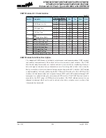
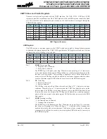
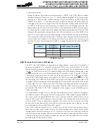
UCR3 register
The UCR3 register is the last of the UART control registers and controls the software reset operation
of the UART module. The only one available bit named URST in the UART control register UCR3
is the UART software reset control bit. When this bit is equal to "0", the UART operates normally.
If this bit is equal to "1", the whole UART module will be reset. When this situation occurs, the
transmitter and receiver will be reset. The UART registers including the status register and control
registers will keep the POR states shown in the above UART registers table after the reset condition
occurs.
Bit
7
6
5
4
3
2
1
0
Name
URST
—
—
—
—
—
—
—
R/W
R/W
—
—
—
—
—
—
—
POR
0
—
—
—
—
—
—
—
Bit 7
URST
: UART software reset
0: No action
1: UART reset occurs
Bit 6~0
Unimplemented, read as “0”
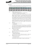
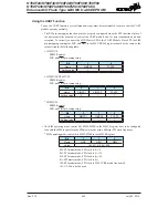
Baud Rate Generator
To setup the speed of the serial data communication, the UART function contains its own dedicated
baud rate generator. The baud rate is controlled by its own internal free running 8-bit timer, the
period of which is determined by two factors. The first of these is the value placed in the baud rate
register BRG and the second is the value of the BRGH bit with the control register UCR2. The
BRGH bit decides if the baud rate generator is to be used in a high speed mode or low speed mode,
which in turn determines the formula that is used to calculate the baud rate. The value N in the BRG
register which is used in the following baud rate calculation formula determines the division factor.
Note that N is the decimal value placed in the BRG register and has a range of between 0 and 255.
UCR2 BRGH Bit
0
1
Ba�d Rate (BR)
f
CLKI
[64 (N+1)]
f
CLKI
[16 (N+1)]
By programming the BRGH bit which allows selection of the related formula and programming the
required value in the BRG register, the required baud rate can be setup. Note that because the actual
baud rate is determined using a discrete value, N, placed in the BRG register, there will be an error
associated between the actual and requested value. The following example shows how the BRG
register value N and the error value can be calculated.


