


Rev. 2.10
23�
���� 02� 201�
Rev. 2.10
235
���� 02� 201�
HT68F20/HT68F30/HT68F40/HT68F50/HT68F60
HT68FU30/HT68FU40/HT68FU50/HT68FU60
Enhanced I/O Flash Type 8-Bit MCU with EEPROM
HT68F20/HT68F30/HT68F40/HT68F50/HT68F60
HT68FU30/HT68FU40/HT68FU50/HT68FU60
Enhanced I/O Flash Type 8-Bit MCU with EEPROM
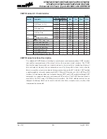
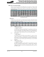
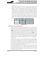
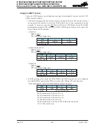
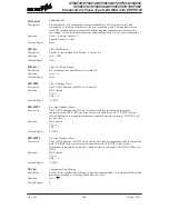
BRG Register
Bit
7
6
5
4
3
2
1
0
Name
BRG7
BRG6
BRG5
BRG�
BRG3
BRG2
BRG1
BRG0
R/W
R/W
R/W
R/W
R/W
R/W
R/W
R/W
R/W
POR
×
×
×
×
×
×
×
×
“×”: �nknown
Bit 7~0
BRG7~BRG0
: Baud Rate values
By programming the BRGH bit in UCR2 Register which allows selection of the
related formula described above and programming the required value in the BRG
register, the required baud rate can be setup.
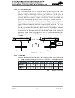
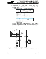
UART Module Setup and Control
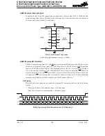
For data transfer, the UART function utilizes a non-return-to-zero, more commonly known as NRZ,
format. This is composed of one start bit, eight or nine data bits and one or two stop bits. Parity
is supported by the UART hardware and can be setup to be even, odd or no parity. For the most
common data format, 8 data bits along with no parity and one stop bit, denoted as 8, N, 1, is used
as the default setting, which is the setting at power-on. The number of data bits and stop bits, along
with the parity, are setup by programming the corresponding BNO, PRT, PREN and STOPS bits in
the UCR1 register. The baud rate used to transmit and receive data is setup using the internal 8-bit
baud rate generator, while the data is transmitted and received LSB first. Although the transmitter
and receiver of the UART are functionally independent, they both use the same data format and baud
rate. In all cases stop bits will be used for data transmission.
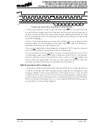
• Enabling/Disabling the UART
The basic on/off function of the internal UART function is controlled using the UARTEN bit in
the UCR1 register. If the UARTEN, TXEN and RXEN bits are set, then these two UART pins
will act as normal TX output pin and RX input pin respectively. If no data is being transmitted on
the TX pin, then it will default to a logic high value.
Clearing the UARTEN bit will disable the TX and RX pins and these two pins will be in the
state of high impedance. When the UART function is disabled, the buffer will be reset to an
empty condition, at the same time discarding any remaining residual data. Disabling the UART
will also reset the enable control, the error and status flags with bits TXEN, RXEN, TXBRK,
RXIF, OERR, FERR, PERR and NF being cleared while bits TIDLE, TXIF and RIDLE will be
set. The remaining control bits in the UCR1, UCR2 and BRG registers will remain unaffected.
If the UARTEN bit in the UCR1 register is cleared while the UART is active, then all pending
transmissions and receptions will be immediately suspended and the UART will be reset to a
condition as defined above. If the UART is then subsequently re-enabled, it will restart again in
the same configuration.


