


Rev. 2.10
160
���� 02� 201�
Rev. 2.10
161
���� 02� 201�
HT68F20/HT68F30/HT68F40/HT68F50/HT68F60
HT68FU30/HT68FU40/HT68FU50/HT68FU60
Enhanced I/O Flash Type 8-Bit MCU with EEPROM
HT68F20/HT68F30/HT68F40/HT68F50/HT68F60
HT68FU30/HT68FU40/HT68FU50/HT68FU60
Enhanced I/O Flash Type 8-Bit MCU with EEPROM
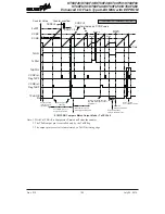
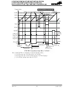
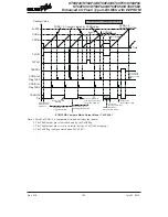
Single Pulse Output Mode
To select this mode, the required bit pairs, TnAM1, TnAM0 and TnBM1, TnBM0 should be set to
10 respectively and also the corresponding TnAIO1, TnAIO0 and TnBIO1, TnBIO0 bits should be
set to 11 respectively. The Single Pulse Output Mode, as the name suggests, will generate a single
shot pulse on the TM output pin.
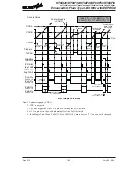
The trigger for the pulse TPnA output leading edge is a low to high transition of the TnON bit, which
can be implemented using the application program. The trigger for the pulse TPnB output leading
edge is a compare match from Comparator B, which can be implemented using the application
program. However in the Single Pulse Mode, the TnON bit can also be made to automatically
change from low to high using the external TCKn pin, which will in turn initiate the Single Pulse
output of TPnA. When the TnON bit transitions to a high level, the counter will start running and
the pulse leading edge of TPnA will be generated. The TnON bit should remain high when the pulse
is in its active state. The generated pulse trailing edge of TPnA and TPnB will be generated when
the TnON bit is cleared to zero, which can be implemented using the application program or when a
compare match occurs from Comparator A.
However a compare match from Comparator A will also automatically clear the TnON bit and thus
generate the Single Pulse output trailing edge of TPnA and TPnB. In this way the CCRA value can
be used to control the pulse width of TPnA. The CCRA-CCRB value can be used to control the
pulse width of TPnB. A compare match from Comparator A and Comparator B will also generate
TM interrupts. The counter can only be reset back to zero when the TnON bit changes from low to
high when the counter restarts. In the Single Pulse Mode CCRP is not used. The TnCCLR bit is also
not used.
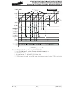
S/W Command
SET
“
TnON
”
or
TCKn Pin
Transition
CCRB
Leading Edge
CCRA
Trailing Edge
S/W Command
CLR
“
TnON
”
or
CCRA Compare
Match
TPnA Output Pin
TPnB Output Pin
Pulse Width = (CCRA-CCRB) Value
Pulse Width = CCRA Value
Counter Value
CCRB
CCRA
0
Time
TnON = 1
CCRB Compare
Match
S/W Command
CLR
“
TnON
”
or
CCRA Compare
Match
CCRB
Trailing Edge
CCRA
Leading Edge
TnON bit
0
®
1
TnON bit
1
®
0
TnON bit
1
®
0
Single Pulse Generation


