


Rev. 2.10
158
���� 02� 201�
Rev. 2.10
159
���� 02� 201�
HT68F20/HT68F30/HT68F40/HT68F50/HT68F60
HT68FU30/HT68FU40/HT68FU50/HT68FU60
Enhanced I/O Flash Type 8-Bit MCU with EEPROM
HT68F20/HT68F30/HT68F40/HT68F50/HT68F60
HT68FU30/HT68FU40/HT68FU50/HT68FU60
Enhanced I/O Flash Type 8-Bit MCU with EEPROM
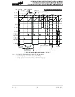
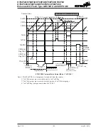
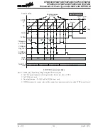
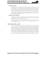
Co�nter Va��e
CCRA
TnON
TnPAU
TnBPOL
CCRB Int.
F�ag TnBF
Time
Co�nter C�eared b� CCRA
Pa�se
Res�me
Stop
Co�nter
Restart
TnCCLR = 1; TnBM [1:0] = 10;
TnPWM [1:0] = 00
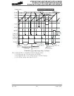
O�tp�t Pin
Reset to
Initia� va��e
O�tp�t contro��ed b�
other pin-shared f�nction
O�tp�t Inverts
when TnBPOL
is high
CCRB
CCRP Int.
F�ag TnPF
TPnB Pin
(TnBOC=1)
TPnB Pin
(TnBOC=0)
D�t� C�c�e
set b� CCRB
PWM Period set b� CCRA
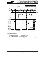
ETM PWM Mode -- Edge Aligned
Note: 1. Here TnCCLR=1 therefore CCRA clears the counter and determines the PWM period
2. The internal PWM function continues running even when TnBIO [1:0]=00 or 01
3. The CCRA controls the TPnB PWM period and CCRB controls the TPnB PWM duty
4. Here the TM pin control register should not enable the TPnA pin as a TM output pin


