12
FireNET FN-DAC Digital Alarm Communicator I & O Manual - v 1.0
NOTE
: All connections must be made with AC power and batteries disconnected to
avoid damage to the equipment!
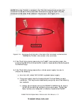
1) Carefully install the communicator circuit board in the FireNET enclosure using
the mounting screws.
NOTE
: As with all electronic components, the circuit board is very sensitive and can be
damaged by electrostatic discharge.
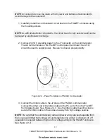
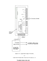
2) Connect 24 VDC operating power to the J7 connector on the communicator.
The AUX 24 terminals on the FireNET control panel (terminals 18 and 19)
should be used to supply power. Be sure to observe proper polarity.
Figure 2.2.2 – Power Terminals on FN-DAC Communicator
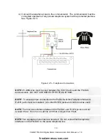
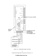
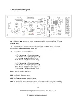
3) Connect the ribbon cable to the J2 plug on the FN-DAC communicator.
Connect the other end of the ribbon cable to the PC port (J5) on the FireNET
front display board. See Figure 2.2.3. Use the ribbon cable mounting clips to
secure the ribbon cable in the enclosure away from high voltage sources.
NOTE
: Be sure that the communicator data and power wiring are kept separate from
the non-power limited high voltage AC and telephone line wiring! A minimum of .25”
separation is required between high and low voltage wiring in the FireNET enclosure.
See Figure 2.2.4.
firealarmresources.com


