background image

ENGINE INSTALLATION

(A) Engine Mount  . . . . . . . . . . . . . . . . . . . . . . . . . . . . . . . .1
(B) 4mmx20mm Screws  . . . . . . . . . . . . . . . . . . . . . . . . . . . . . . .4
(C) Mounting Plates  . . . . . . . . . . . . . . . . . . . . . . . . . . . . . . .2
(D) 4mmx15mm Screws  . . . . . . . . . . . . . . . . . . . . . . . . . . . . . .4
(E) 4mm Washers  . . . . . . . . . . . . . . . . . . . . . . . . . . . . . . . . . .4
(F) Lock Washers  . . . . . . . . . . . . . . . . . . . . . . . . . . . . . . . . . .4
(G) 3.5mm Screw  . . . . . . . . . . . . . . . . . . . . . . . . . . . . . . . . . .4
(H) 3.5mm Nuts  . . . . . . . . . . . . . . . . . . . . . . . . . . . . . . . . . . .4

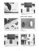
(3) Hold each mounting plate under one engine mount as shown (Thick side

towards the engine ) Line up the mark with the front hole of the engine mount.
Mark the plates where the engine mounting holes are.

(1) Install the engine mount to the fuselage using (4) 4mmx20mm screws Note

the direction the mount is installed for proper engine positioning Also use
screw locking compound on the screw threads.

(4) Drill two 3.5mm holes in each mounting plate at the marks.

(2) Make a mark 1/2" to 5/8" back from the hole on one end of each mounting

plate using a sharp knife NOTE: When mounting the engine, the thicker
sides of the plates should be mounted facing the engine

(5) Mount the plates to the engine using the  3 . 5 m m screws and lock washers up

from the bottom as shown. Next apply screw locking compound to the screw
threads and tighten on the 3.5mm nuts. Now do this to both sides.

-10-

Содержание Diabolo 40

Страница 1: ...MODEL SPECIAL COVERING PROCESS YIELDS A STRONG BRILLIANT AND FUEL PROOF FINISH 90 COMPLETE OUT OF THE BOX NO SANDING PAINTING OR FINISHING REQUIRED SMOOTH STEADY FLIGHT CHARACTERISTICS JUST LIKE A RE...

Страница 2: ...ts Do not use too much as it may run and spoil the appearance Do not get Cyanoacrylate on the foam parts of the Diabolo Cyanoacrylate will destroy the foam 3 It is best to use 30 minute epoxy where re...

Страница 3: ...29 Rear Wing Joiner 30 Front Wing Joiner 31 RubberShock Absorber 32 Cowl Brace 33 Aileron Servo Tray Mount 34 Aileron Servo Tray 35 8mm Dowel Rod 36 Wing Bolt Mounting Block 37 Balsa Tank Support 38...

Страница 4: ...ron Servo Tray 1 N Aileron Servo Tray Mount 1 0 Main Servo Tray 1 1 Check each wing half for smooth aileron operation It is a good ideal to exercise move back and forth the ailerons to insure easy def...

Страница 5: ...off any excess glue Hold the two wing halves firmly together with tape until the epoxy has cured 10 EpoxytheIwo dowel rodsintothe holes Make suretheyareall theway in 8 Once dry remove the tape Positi...

Страница 6: ...selage The blind nuts should face down 16 After the epoxy has cured place the wing into the fuselage as shown Put the front in first aligning the dowel rods in the holes Once in place lower the back i...

Страница 7: ...her wing o ring and temporarily fasten down the wing Check for good fit and then remove A Cockpit 1 B Canopy 1 C Cockpit Mounts 4 D 3x8mm Self Tapping Screws 4 20 Trial fit the aileron servo tray moun...

Страница 8: ...x12mm Screw 2 K 3mm Washer 2 L 3mm Nut 2 M Plastic Collar 2 3 Trail fit the canopy to the cockpit If necessary trim for a perfect fit Apply a thin bead of Cyanoacrylate glue to the cockpit and attach...

Страница 9: ...wo wheel pants and drill two holes in each one The first hole should be at the indent 4mm in diameter The second should be 3 8 above the first and smaller 3mm diameter 7 Flare open the pants and inser...

Страница 10: ...mmx20mm screws Note the direction the mount is installed for proper engine positioning Also use screw locking compound on the screw threads 4 Drill two 3 5mm holes in each mounting plate at the marks...

Страница 11: ...E Plastic Disc Large 1 F Plastic Disc Small 1 G 3mmx 18mm Self Tapping Screw 1 H Rubber Plug 1 I Neoprene Ring 1 J Balsa Tank Support 1 3 Attach the silicone tubing to the centered fuel pipe and attac...

Страница 12: ...ing to the tank with silicone sealer Attach two pieces of fuel tubing 6 each to the pipes One is for the carburetor the other is for the pressure tap on the muffler 9 Epoxy the tank support to the ins...

Страница 13: ...de on the retaining tubes After checking the neutral position of the aileron servo and ailerons put a mark on the push rods where the servo arm holes are 2 Screw the aileron horns onto the aileron con...

Страница 14: ...e easily accessible 8 Connect the aileron servo to the receiver and check the movement of the ailerons Make sure that both ailerons are neutral when the servo is neutral Adjust the clevises as needed...

Страница 15: ...e rod of both wood push rods and with a hobby knife Carefully cut straight grooves from the holes to the ends Only cut a groove on one side of each end except for one end of one rod the one with two h...

Страница 16: ...the servos after the tail assembly 23 Make a Z bend on one end of the throttle control rod and insert the opposite end into the tube 21 Use the throttle control rod and the white throttle tube for the...

Страница 17: ...l move from low to high completely ASSEMBLY OF THE TAIL SECTION 27 From the inside pull back the throttle control rod so the carburetor is closed Now mark the rod where it crosses the throttle servo h...

Страница 18: ...the string from side to side 2 Trim away part of the plastic rear cover to allow proper fit of the horizontal stabilizer 5 Next remove the stabilizer and apply epoxy to the wedge Reinstall the stabili...

Страница 19: ...he wheel collar to hold the wheel on 8 While the epoxy is still wet position the plastic stabilizer root cover over the fin Double check the positioning of the fin after doing this 11 Carefully turn o...

Страница 20: ...cluded hardware and drill 2mm holes for mounting 17 Notch a small groove 1 8 deep from the hole down to the bottom for the tail control arm 15 Trial fit the rudder onto the vertical fin Notice where t...

Страница 21: ...a n g l e d 2 D Mounting Plates A n g l e d 4 E Brass Tubes 6 F 2mmx20mm Screws 6 G Clevis Retainer Tube 1 H Rod Clevis 3 3 Using the control horns as a guide center and mark two holes for drilling on...

Страница 22: ...the tubes and finally thread them into the back plates See the picture for proper positioning 9 Attach the respective control rods to each horn Use the middle hole of the horn Turn on the radio system...

Страница 23: ...wn in the above drawing You may need to enlarge the holes 2 Trim away some of the plastic from under the front of the fuselage where shown COWL AND PROP INSTALLATION A Cowl 1 B Cowl Brace 1 C 3mmx8mm...

Страница 24: ...it Now make two holes in the side and the top where the cylinder head and needle valve are located for easy accessibility 8 Remove the crankshaft nut and washer and install the spinner back plate onto...

Страница 25: ...k up the servos and wrap the receiver and battery in natural foam rubber to protect it from vibration Goldberg 481 Foam Rubber 1 4 works well Use the aileron extension for Channel 1 4 Make a small kno...

Страница 26: ...ortant aspect of setting up the airplane properly It will control a large part of what type of flying characteristics your plane will have If it s nose heavy the airplane will try to dive and the elev...

Страница 27: ...easier Do not use bare hands fingers for starting as the kick back from a model engine can be strong enough to cause severe injury 8 Attach the glow plug clip at this time 9 With quick flipping moveme...

Страница 28: ...power to reach the landing area If the plane is too high apply power and climb back up to some altitude and set up to land again With practice you will be flying with more confidence and able to make...

Отзывы: