background image

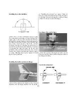
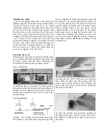
Attaching the elevator control horn

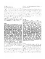
Locating the rudder exit hole

Locate a nylon control horn. Place the horn on

the bottom of the elevator. Position it 1" (25.4mm)
from center and aligned with the leading edge as
shown in the sketch and photo. Mark the two holes

with a felt-tip pen. The holes of the control horn

should line-up with the gap between the rudder
and the vertical stabilizer. Drill two 1/16" (1.5mm)
holes through the balsa elevator. Insert two 2-56 x
5/8" machine screws through the control horn and
elevator into the control horn back plate on the
opposite side of the elevator. Tighten the screws

but do not crush the balsa.

QThe precut rudder pushrod exit hole is located on
the same side as the rudder control horn, under the
covering. Locate the exit hole by gently running
your finger down the top of the fuselage. Using a
hobby knife, remove the covering from the rudder
pushrod exit hole. Do not remove the covering from
the exit hole on the opposite side.

Cutting the elevator exit hole

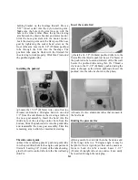
Installing the rudder horn
Locate the other nylon control horn. Place the
control horn on the left side of the rudder, 1" (25mm)
from the top of the hinged stabilizer as shown in the
photo on the previous page. Mark the two holes with
a felt-tip pen. Drill two 1/16" (1.5mm) holes through
the rudder. Use two machine screws 2-56 x 5/8" to
attach the control horn.

Q The precut elevator pushrod exit hole is located

on the same side of the fuselage as the elevator
control horn, beneath the covering. Locate the exit
hole by gently running your finger down the side of
the fuselage over the covering. Using a hobby knife,
remove the covering from the elevator pushrod

exit hole. Do not remove the covering from the exit
hole on the opposite side of the fuselage.

12

Содержание Avistar

Страница 1: ...instructions below when returning your model This will help our experienced technicians to repair and return it as quickly as possible 1 ALWAYS return your entire system including airplane and radio 2...

Страница 2: ...tighten completely until later 9 16 3 On page 17 at step 36 install the nose gear strut through the steering arm followed by a 4mm collar Next slide the strut through the lower lug on the engine moun...

Страница 3: ...he Avistar 40 s assembly instructions will be quite easy if you identify and organize the parts before you begin 1 RUDDER FIN C 2 STABILIZER ELEVATOR C 3 LEFT WING PANEL A 4 RIGHT WING PANEL A 5 FUEL...

Страница 4: ...dy for takeoff in as little as 15 20 hours Your hobby dealer or flying instructor can help you decide what accessories you ll need for flight Most are one time only purchases and your instructor will...

Страница 5: ...age or defects caused by misuse or improper assembly service or shipment Modifications alterations or repair by anyone other than Hobby Services voids this warranty We are sorry but we cannot be respo...

Страница 6: ...epoxy on one side of a wing joiner Stack the other joiner on top of the epoxy Clamping the wing joiner l l Use three clothes pins to clamp the wing joiners together firmly The excess epoxy must be re...

Страница 7: ...n the joiner plate Be sure you are installing the joiner in the correct orientation to the wing It should angle upwards when installed correctly Clean the excess epoxy from the wing root rib You must...

Страница 8: ...ng Installing the servo tray J Mix l 8oz 3 5ml of 6 minute epoxy to glue the servo tray to the bottom side of the wing Apply equal amounts of epoxy to the mounting blocks on both ends ofthe servo tray...

Страница 9: ......

Страница 10: ...e fuselage and remove the covering over each hole Insert the two wood dowels into the fuselage The shorter dowel is installed towards the tail of the airplane Install the dowel caps onto the dowels us...

Страница 11: ...emove the covering from the center of the horizontal stabilizer Do not cut into the balsa sheeting on the horizontal stabilizer Installing the stabilizer Q Mix l 4oz 7 5ml of30 minute epoxy to install...

Страница 12: ...ilizer when viewed from the back It is critical that the fin remains perpendicular while the epoxy is curing Masking tape may be required to hold the fin during this time Installing the rudder and ele...

Страница 13: ...ly running your finger down the top of the fuselage Using a hobby knife remove the covering from the rudder pushrod exit hole Do not remove the covering from the exit hole on the opposite side Cutting...

Страница 14: ...our 2x3 8 self tapping screws to the bottom of the fuselage over the struts The struts should be flush with the bottom of the fuselage Mounting the wheels Q Locate two foam wheels and four wheel colla...

Страница 15: ...hrod wire into the guide tube and reassemble the nose gear assembly Trim the remaining arm to allow for maximum steering Throttle control guide Q Insert the remaining plastic pushrod guide tube into t...

Страница 16: ...l not touch the end of the fuel tank The plug assembly can now be inserted into the tank The pressure tube should be adjusted so the tube is pointed straight up just under the top of the tank Caution...

Страница 17: ...to the fuel inlet pressure line to the muffler Mounting the propeller and spinner Q Slide the spinner backplate onto the crankshaft of the engine Align the propellerwith the two alignment pegs on the...

Страница 18: ...ufacturer s manual for more detailed instructions Notice the location and orientation of each servo as well as the switch location Antenna Routing STRAIN RELIEF INSIDE FUSELAGE ANTENNA HOLDER AT THE T...

Страница 19: ...ith a nylon FasLink Q Repeat the above step for the rudder pushrod 1 1 Adjust the height of the pushrod support so the pushrods can move freely without binding Glue the brace into position using mediu...

Страница 20: ...s tail heavy and you must move the battery and or the receiver toward the nose to achieve balance Ifthe nose drops it s nose heavy and you must move the battery and or receiver toward the tail to achi...

Страница 21: ...rease it Ground Stance NOSE TOO HIGH NOSE TOO LOW LEVEL Q Eyeball the side of the fuselage from 6 10 feet away If necessary adjust the height of the nose by raising or lowering the nose gear wire so t...

Страница 22: ...friend stand by your model and while you work the controls tell you what the control surfaces are doing Repeat this test with the engine running at various speeds with a helper holding the model If th...

Страница 23: ......

Страница 24: ......

Страница 25: ...latively constant Keep holding up elevator until the plane is level then slowly release the sticks You re done It s really that easy CAUTION THIS APPLIES TO ALL R C AIRPLANES If while flying you notic...

Отзывы: