


SYSTEM / Control System
T2-1-54
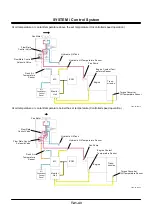
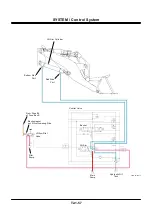
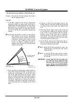
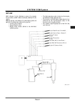
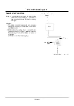
Bucket Auto-Leveler Control
Purpose: Automatically to tilt the bucket at a proper
angle (horizontal) to start digging when re-
turning the bucket to the tilting position
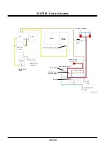
Operation:
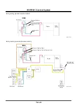
1. When bucket dump operation is carried out, the
bar is located in front of the bucket proximity
switch.
While the bar passes near the bucket proximity
switch, the bucket proximity switch is turned ON.
This excites the leveler relay and electromagnet at
the bucket tilt side in the pilot valve.
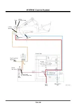
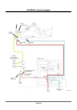
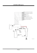
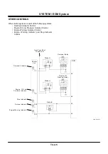
2. When the bucket control lever is moved farther
than the bucket tilting detent position (position to
move farther than the tilting position), the bucket
control lever is retained by the electromagnet on
the bucket tilting side, and pressure oil from the
pilot valve moves the bucket spool in the control
valve.
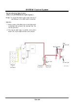
3. Pressure oil from the main pump flows to the
bottom side of the bucket cylinder through the
bucket spool in the control valve, and extends the
bucket cylinder. When the bucket cylinder is ex-
tended, the bar also passes by the bucket prox-
imity switch at the same time.
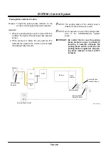
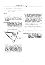
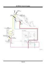
4. When the bar moves apart from the bucket prox-
imity switch, the bucket proximity switch is turned
OFF. As the leveler relay and the electromagnet at
the bucket tilt side are unexcited, the bucket con-
trol lever is returned to the neutral position. As the
bucket spool in the control valve also returns to
neutral, the bucket cylinder stops. Consequently,
the bucket is kept at the proper digging angle
(horizontal).
Содержание ZW180
Страница 1: ......
Страница 2: ......
Страница 8: ...4GDT 1 2 Blank ...
Страница 10: ...GENERAL Specification T1 1 2 Blank ...
Страница 38: ...GENERAL Component Specifications T1 3 14 Blank ...
Страница 39: ...MEMO ...
Страница 40: ...MEMO ...
Страница 42: ...4GDT 2 2 Blank ...
Страница 56: ...SYSTEM Control System T2 1 14 Blank ...
Страница 82: ...SYSTEM Control System T2 1 40 Blank ...
Страница 92: ...SYSTEM Control System T2 1 50 Blank ...
Страница 106: ...SYSTEM Control System T2 1 64 Blank ...
Страница 116: ...SYSTEM ECM System T2 2 10 Blank ...
Страница 128: ...SYSTEM Hydraulic System T2 3 12 Blank ...
Страница 147: ...SYSTEM Hydraulic System T2 3 31 Blank ...
Страница 150: ...SYSTEM Hydraulic System T2 3 34 Blank ...
Страница 165: ...SYSTEM Electrical System T2 4 15 T4GD 02 04 019 Battery Relay Battery SC FC L L B E D Alternator B Regulator F R ...
Страница 184: ...SYSTEM Electric System T2 4 34 Blank ...
Страница 185: ...MEMO ...
Страница 186: ...MEMO ...
Страница 195: ...COMPONENT OPERATION Pump Device T3 1 7 Blank ...
Страница 210: ...COMPONENT OPERATION Control Valve T3 2 2 Component Layout T4GB 03 02 003 1 2 3 4 5 7 8 9 10 11 7 6 ...
Страница 212: ...COMPONENT OPERATION Control Valve T3 2 4 T4GB 03 02 003 1 2 3 4 5 7 8 9 10 11 7 6 ...
Страница 214: ...COMPONENT OPERATION Control Valve T3 2 6 T4GB 03 02 003 1 2 3 4 5 7 8 9 10 11 7 6 ...
Страница 226: ...COMPONENT OPERATION Control Valve T3 2 18 Blank ...
Страница 232: ...COMPONENT OPERATION Control Valve T3 2 24 Blank ...
Страница 239: ...COMPONENT OPERATION Hydraulic Fan Motor T3 3 7 T4GB 03 03 005 7 8 From Fan Pump P B A 12 T To Hydraulic Oil Tank ...
Страница 248: ...COMPONENT OPERATION Steering Pilot Valve T3 4 6 Blank ...
Страница 258: ...COMPONENT OPERATION Steering Valve T3 5 10 Blank ...
Страница 274: ...COMPONENT OPERATION Pilot Valve T3 6 16 Blank ...
Страница 282: ...COMPONENT OPERATION Pilot Valve T3 6 24 Blank ...
Страница 299: ...COMPONENT OPERATION Ride Control Valve T3 8 5 Blank ...
Страница 306: ...COMPONENT OPERATION Ride Control Valve T3 8 12 Blank ...
Страница 316: ...COMPONENT OPERATION Drive Unit T3 9 10 Forward Clutch Shaft T4GD 03 09 005 Reverse Clutch Shaft T4GD 03 09 006 ...
Страница 345: ...COMPONENT OPERATION Drive Unit T3 9 39 T107 02 07 005 1 Spool 2 Spring 3 Solenoid T P S a a 1 2 3 ...
Страница 348: ...COMPONENT OPERATION Drive Unit T3 9 42 Blank ...
Страница 371: ...MEMO ...
Страница 372: ...MEMO ...
Страница 374: ......


