


SYSTEM / ECM System
T2-2-8
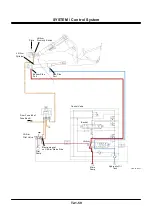
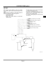
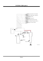
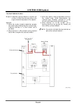
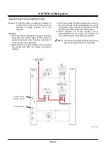
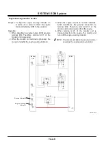
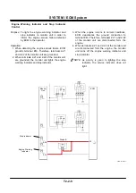
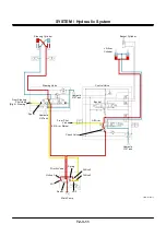
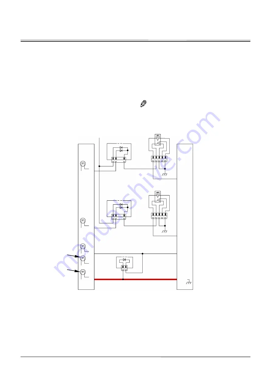
Engine Warning Indicator Control
Purpose: To light the engine warning indicator on
monitor unit in order to inform the engine
failure detected by ECM to the operator.
Operation:
1. When detecting the engine failure, ECM grounds
terminal #44. Therefore, terminal 2-21 of the
monitor unit is grounded.
2. When the monitor unit terminal is grounded, the
monitor unit lights the engine warning indicator.
3. When the engine returns to normal conditions,
ECM deactivates the ground connection to
terminal #44. Therefore, terminal 2-21 of the
monitor unit is disconnected form the engine.
4. When terminal 2-21 of the monitor unit is
disconnected form the engine, the monitor unit
turns off the engine warning indicator.
NOTE: The monitor unit lights the service indicator
as well as the engine warning indicator.
T4GD-02-02-008
ECM
Monitor
Unit
Diode B
44
2-21
Service Indicator
Engine Warning
Indicator
Содержание ZW180
Страница 1: ......
Страница 2: ......
Страница 8: ...4GDT 1 2 Blank ...
Страница 10: ...GENERAL Specification T1 1 2 Blank ...
Страница 38: ...GENERAL Component Specifications T1 3 14 Blank ...
Страница 39: ...MEMO ...
Страница 40: ...MEMO ...
Страница 42: ...4GDT 2 2 Blank ...
Страница 56: ...SYSTEM Control System T2 1 14 Blank ...
Страница 82: ...SYSTEM Control System T2 1 40 Blank ...
Страница 92: ...SYSTEM Control System T2 1 50 Blank ...
Страница 106: ...SYSTEM Control System T2 1 64 Blank ...
Страница 116: ...SYSTEM ECM System T2 2 10 Blank ...
Страница 128: ...SYSTEM Hydraulic System T2 3 12 Blank ...
Страница 147: ...SYSTEM Hydraulic System T2 3 31 Blank ...
Страница 150: ...SYSTEM Hydraulic System T2 3 34 Blank ...
Страница 165: ...SYSTEM Electrical System T2 4 15 T4GD 02 04 019 Battery Relay Battery SC FC L L B E D Alternator B Regulator F R ...
Страница 184: ...SYSTEM Electric System T2 4 34 Blank ...
Страница 185: ...MEMO ...
Страница 186: ...MEMO ...
Страница 195: ...COMPONENT OPERATION Pump Device T3 1 7 Blank ...
Страница 210: ...COMPONENT OPERATION Control Valve T3 2 2 Component Layout T4GB 03 02 003 1 2 3 4 5 7 8 9 10 11 7 6 ...
Страница 212: ...COMPONENT OPERATION Control Valve T3 2 4 T4GB 03 02 003 1 2 3 4 5 7 8 9 10 11 7 6 ...
Страница 214: ...COMPONENT OPERATION Control Valve T3 2 6 T4GB 03 02 003 1 2 3 4 5 7 8 9 10 11 7 6 ...
Страница 226: ...COMPONENT OPERATION Control Valve T3 2 18 Blank ...
Страница 232: ...COMPONENT OPERATION Control Valve T3 2 24 Blank ...
Страница 239: ...COMPONENT OPERATION Hydraulic Fan Motor T3 3 7 T4GB 03 03 005 7 8 From Fan Pump P B A 12 T To Hydraulic Oil Tank ...
Страница 248: ...COMPONENT OPERATION Steering Pilot Valve T3 4 6 Blank ...
Страница 258: ...COMPONENT OPERATION Steering Valve T3 5 10 Blank ...
Страница 274: ...COMPONENT OPERATION Pilot Valve T3 6 16 Blank ...
Страница 282: ...COMPONENT OPERATION Pilot Valve T3 6 24 Blank ...
Страница 299: ...COMPONENT OPERATION Ride Control Valve T3 8 5 Blank ...
Страница 306: ...COMPONENT OPERATION Ride Control Valve T3 8 12 Blank ...
Страница 316: ...COMPONENT OPERATION Drive Unit T3 9 10 Forward Clutch Shaft T4GD 03 09 005 Reverse Clutch Shaft T4GD 03 09 006 ...
Страница 345: ...COMPONENT OPERATION Drive Unit T3 9 39 T107 02 07 005 1 Spool 2 Spring 3 Solenoid T P S a a 1 2 3 ...
Страница 348: ...COMPONENT OPERATION Drive Unit T3 9 42 Blank ...
Страница 371: ...MEMO ...
Страница 372: ...MEMO ...
Страница 374: ......


