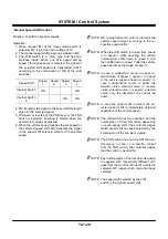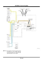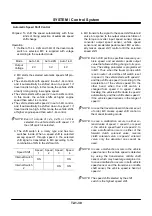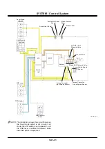
SYSTEM / Control System
T2-1-30
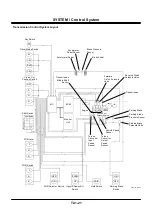
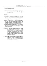
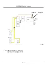
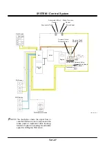
Automatic Speed Shift Control
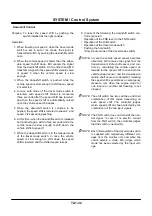
Purpose: To shift the speed automatically with three
kinds of timing selection of automatic speed
shift change
Operation:
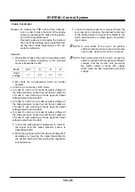
1. If either of 1-4L, 2-4N and 1-4H of the travel mode
switch is selected, MC is supplied with votage
according to the selected mode.
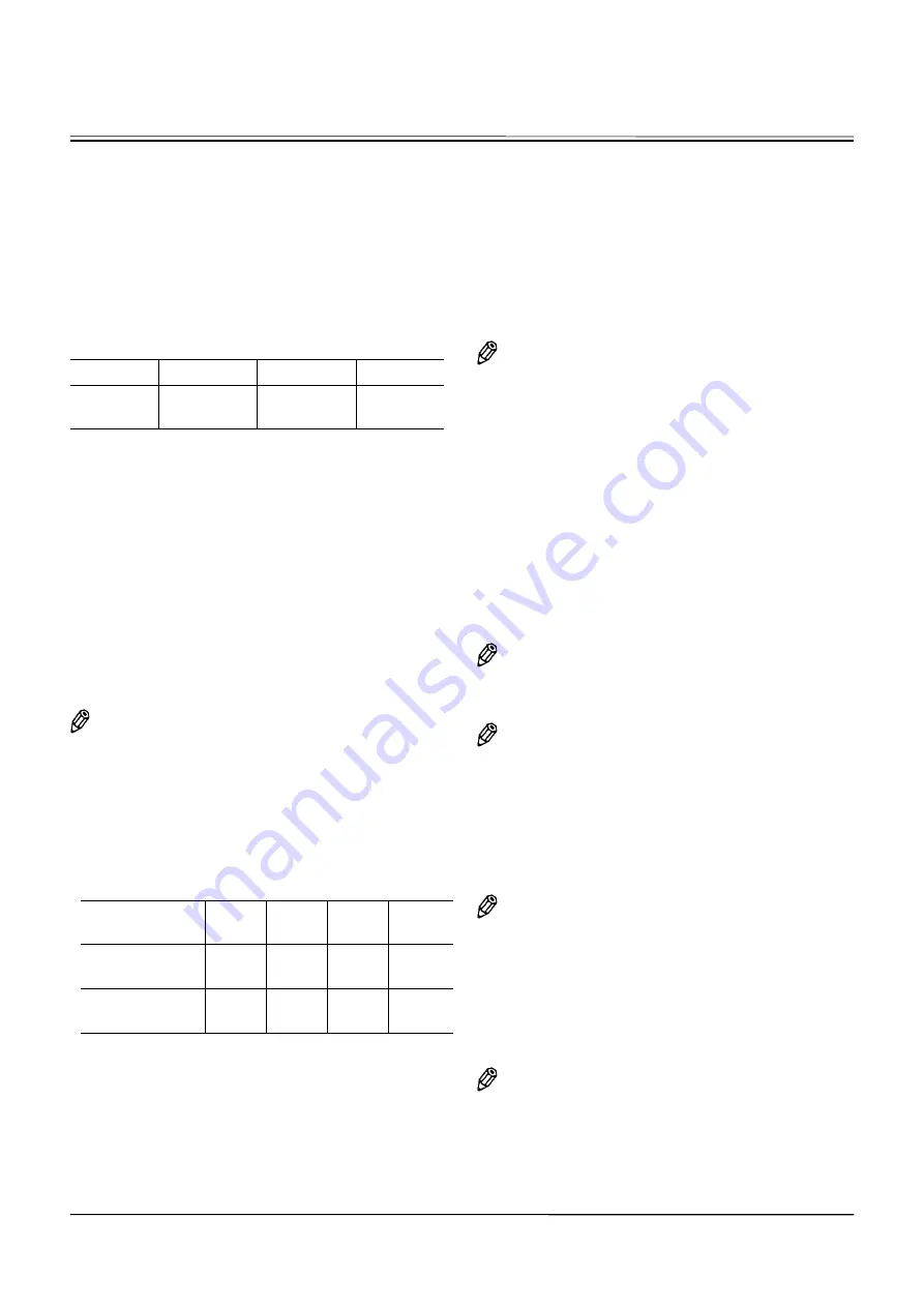
Mode
Auto 1-4L
Auto 2-4N
Auto 1-4H
Output
Voltage
2 V
3 V
4 V
2. MC starts the selected automatic speed shift pro-
gram.
•
The vehicle starts with speed 2 in auto 1-4L control,
and it automatically be shifted down to speed 1 if
travel load is too high. In this mode, the vehicle shifts
at early timing during low engine speed.
•
The vehicle starts with speed 2 in auto 2-4N control.
In this mode, the vehicle shifts at higher engine
speed than auto 1-4L control.
•
The vehicle starts with speed 2 in auto 1-4H control,
and it automatically be shifted down to speed 1 if
travel load is too high. In this mode, the vehicle shifts
at higher engine speed than auto 1-4L control.
NOTE: Even if a mode of 1-4L, 2-4N, or 1-4H is
selected, the vehicle starts with speed 1 if
the shift switch is selected.
3. The shift switch is a rotary type and has two
switches inside. When a speed shift is selected
among speed 1 through speed 4, the selected
shift signal is transmitted to MC according to the
combination of ON in the shift switch.
Speed Shift
Speed
1
Speed
2
Speed
3
Speed
4
Internal Switch
1
ON ON
Internal Switch
2
ON
ON
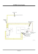
4. MC transmits the signal to the speed shift solenoid
valve in response to the output value each time of
the torque converter input speed sensor, torque
converter output speed sensor, vehicle speed
sensor and accelerater pedal sensor. MC eventu-
ally makes speed shift control until the selected
speed shift.
NOTE: Each shift position specifies necessary ve-
hicle speed and accelerator pedal output
value that allows shifting change to its posi-
tion. The setting parameter is programmed
in MC. Thus, when the travel mode switch
is set in auto 1-4L and the shift switch is set
in speed 3, the vehicle starts with speed 2,
and then shifts up speed 3 according to the
acceleration of the vehicle speed. On the
other hand, when the shift switch is
changed from speed 3 to speed 1 while
traveling, the vehicle shifts down to speed 2
automatically, and then shifts down speed 1
if the vehicle speed reduces in the range of
speed 1.
NOTE: In case the travel mode switch becomes out
of order, MC makes speed shift control in
the manual traveling mode.
NOTE: In case a malfunction occurs in either so-
lenoid valve of speed 1, speed 3, or speed
4, the vehicle speed fixed is at speed 2. In
case a malfunction occurs in either of the
forward clutch solenoid valve, reverse
clutch solenoid valve, or speed 2 solenoid
valve, only the abnormal one cannot be
used.
NOTE: In case a malfunction occurs in the vehicle
speed sensor, the vehicle speed is detected
by using the transmission middle shaft
sensor, which may have large margin error.
In case a malfunction occurs in both vehicle
speed sensor and the transmission middle
shaft sensor, the vehicle speed is fixed at
speed 2.
NOTE: The speed shift selected by the shift
switch is the highest speed shift.
Содержание ZW180
Страница 1: ......
Страница 2: ......
Страница 8: ...4GDT 1 2 Blank ...
Страница 10: ...GENERAL Specification T1 1 2 Blank ...
Страница 38: ...GENERAL Component Specifications T1 3 14 Blank ...
Страница 39: ...MEMO ...
Страница 40: ...MEMO ...
Страница 42: ...4GDT 2 2 Blank ...
Страница 56: ...SYSTEM Control System T2 1 14 Blank ...
Страница 82: ...SYSTEM Control System T2 1 40 Blank ...
Страница 92: ...SYSTEM Control System T2 1 50 Blank ...
Страница 106: ...SYSTEM Control System T2 1 64 Blank ...
Страница 116: ...SYSTEM ECM System T2 2 10 Blank ...
Страница 128: ...SYSTEM Hydraulic System T2 3 12 Blank ...
Страница 147: ...SYSTEM Hydraulic System T2 3 31 Blank ...
Страница 150: ...SYSTEM Hydraulic System T2 3 34 Blank ...
Страница 165: ...SYSTEM Electrical System T2 4 15 T4GD 02 04 019 Battery Relay Battery SC FC L L B E D Alternator B Regulator F R ...
Страница 184: ...SYSTEM Electric System T2 4 34 Blank ...
Страница 185: ...MEMO ...
Страница 186: ...MEMO ...
Страница 195: ...COMPONENT OPERATION Pump Device T3 1 7 Blank ...
Страница 210: ...COMPONENT OPERATION Control Valve T3 2 2 Component Layout T4GB 03 02 003 1 2 3 4 5 7 8 9 10 11 7 6 ...
Страница 212: ...COMPONENT OPERATION Control Valve T3 2 4 T4GB 03 02 003 1 2 3 4 5 7 8 9 10 11 7 6 ...
Страница 214: ...COMPONENT OPERATION Control Valve T3 2 6 T4GB 03 02 003 1 2 3 4 5 7 8 9 10 11 7 6 ...
Страница 226: ...COMPONENT OPERATION Control Valve T3 2 18 Blank ...
Страница 232: ...COMPONENT OPERATION Control Valve T3 2 24 Blank ...
Страница 239: ...COMPONENT OPERATION Hydraulic Fan Motor T3 3 7 T4GB 03 03 005 7 8 From Fan Pump P B A 12 T To Hydraulic Oil Tank ...
Страница 248: ...COMPONENT OPERATION Steering Pilot Valve T3 4 6 Blank ...
Страница 258: ...COMPONENT OPERATION Steering Valve T3 5 10 Blank ...
Страница 274: ...COMPONENT OPERATION Pilot Valve T3 6 16 Blank ...
Страница 282: ...COMPONENT OPERATION Pilot Valve T3 6 24 Blank ...
Страница 299: ...COMPONENT OPERATION Ride Control Valve T3 8 5 Blank ...
Страница 306: ...COMPONENT OPERATION Ride Control Valve T3 8 12 Blank ...
Страница 316: ...COMPONENT OPERATION Drive Unit T3 9 10 Forward Clutch Shaft T4GD 03 09 005 Reverse Clutch Shaft T4GD 03 09 006 ...
Страница 345: ...COMPONENT OPERATION Drive Unit T3 9 39 T107 02 07 005 1 Spool 2 Spring 3 Solenoid T P S a a 1 2 3 ...
Страница 348: ...COMPONENT OPERATION Drive Unit T3 9 42 Blank ...
Страница 371: ...MEMO ...
Страница 372: ...MEMO ...
Страница 374: ......


