


SYSTEM / Electrical System
T2-4-10
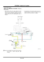
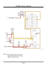
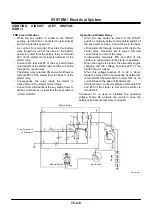
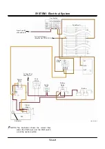
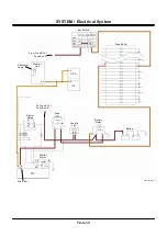
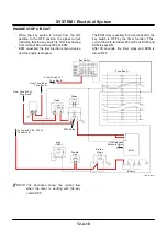
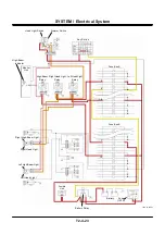
FNR Lever at Operated Position
•
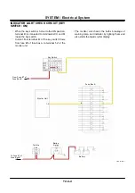
Starting Circuit (Neutral Relay)
•
When the key switch is turned to the START
position, terminal B is connected to terminals M
and ST inside the key switch.
•
Current from terminal ST of the key switch flows
to the neutral relay. Current from terminal M of the
key switch flows to fuse #8 of fuse box A and
excites the battery relay.
•
By exciting the battery relay, the battery power
flows to terminals B of the starter motor and the
starter relay.
•
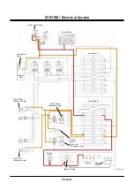
At this time, when either of the FNR lever or the
FNR switch is in the forward or reverse position,
terminal A-27 of MC is connected to the ground
and the neutral relay is excited.
•
By exciting the neutral relay, the circuit between
the neutral relay and terminal S of the starter relay
is blocked.
•
Therefore, when either of the FNR lever and the
FNR switch is at forward or reverse, the starter
motor is not operated although the key switch is
turned to the START position.
Содержание ZW180
Страница 1: ......
Страница 2: ......
Страница 8: ...4GDT 1 2 Blank ...
Страница 10: ...GENERAL Specification T1 1 2 Blank ...
Страница 38: ...GENERAL Component Specifications T1 3 14 Blank ...
Страница 39: ...MEMO ...
Страница 40: ...MEMO ...
Страница 42: ...4GDT 2 2 Blank ...
Страница 56: ...SYSTEM Control System T2 1 14 Blank ...
Страница 82: ...SYSTEM Control System T2 1 40 Blank ...
Страница 92: ...SYSTEM Control System T2 1 50 Blank ...
Страница 106: ...SYSTEM Control System T2 1 64 Blank ...
Страница 116: ...SYSTEM ECM System T2 2 10 Blank ...
Страница 128: ...SYSTEM Hydraulic System T2 3 12 Blank ...
Страница 147: ...SYSTEM Hydraulic System T2 3 31 Blank ...
Страница 150: ...SYSTEM Hydraulic System T2 3 34 Blank ...
Страница 165: ...SYSTEM Electrical System T2 4 15 T4GD 02 04 019 Battery Relay Battery SC FC L L B E D Alternator B Regulator F R ...
Страница 184: ...SYSTEM Electric System T2 4 34 Blank ...
Страница 185: ...MEMO ...
Страница 186: ...MEMO ...
Страница 195: ...COMPONENT OPERATION Pump Device T3 1 7 Blank ...
Страница 210: ...COMPONENT OPERATION Control Valve T3 2 2 Component Layout T4GB 03 02 003 1 2 3 4 5 7 8 9 10 11 7 6 ...
Страница 212: ...COMPONENT OPERATION Control Valve T3 2 4 T4GB 03 02 003 1 2 3 4 5 7 8 9 10 11 7 6 ...
Страница 214: ...COMPONENT OPERATION Control Valve T3 2 6 T4GB 03 02 003 1 2 3 4 5 7 8 9 10 11 7 6 ...
Страница 226: ...COMPONENT OPERATION Control Valve T3 2 18 Blank ...
Страница 232: ...COMPONENT OPERATION Control Valve T3 2 24 Blank ...
Страница 239: ...COMPONENT OPERATION Hydraulic Fan Motor T3 3 7 T4GB 03 03 005 7 8 From Fan Pump P B A 12 T To Hydraulic Oil Tank ...
Страница 248: ...COMPONENT OPERATION Steering Pilot Valve T3 4 6 Blank ...
Страница 258: ...COMPONENT OPERATION Steering Valve T3 5 10 Blank ...
Страница 274: ...COMPONENT OPERATION Pilot Valve T3 6 16 Blank ...
Страница 282: ...COMPONENT OPERATION Pilot Valve T3 6 24 Blank ...
Страница 299: ...COMPONENT OPERATION Ride Control Valve T3 8 5 Blank ...
Страница 306: ...COMPONENT OPERATION Ride Control Valve T3 8 12 Blank ...
Страница 316: ...COMPONENT OPERATION Drive Unit T3 9 10 Forward Clutch Shaft T4GD 03 09 005 Reverse Clutch Shaft T4GD 03 09 006 ...
Страница 345: ...COMPONENT OPERATION Drive Unit T3 9 39 T107 02 07 005 1 Spool 2 Spring 3 Solenoid T P S a a 1 2 3 ...
Страница 348: ...COMPONENT OPERATION Drive Unit T3 9 42 Blank ...
Страница 371: ...MEMO ...
Страница 372: ...MEMO ...
Страница 374: ......


