


SYSTEM / Hydraulic System
T2-3-24
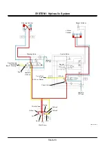
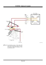
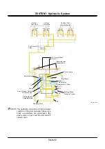
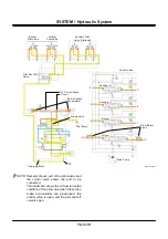
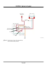
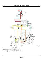
Ride Control Circuit (Optional)
(Refer to SYSTEM / Control System Electric / the
Hydraulic Combined Circuit Control in group.)
•
In front attachment operation, operating pressure
from the lift arm cylinders is accumulated in the
ride control accumulator through the charge cut
spool.
•
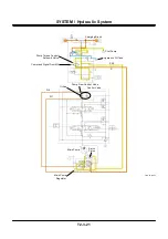
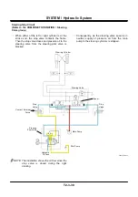
When the ride control switch is turned ON, the
ride control solenoid valve is excited, and the
spool moves downward.
•
As the bottom end of the lift arm cylinder is
connected to the ride control accumulator, the rod
side of the lift arm cylinder is connected to the
hydraulic oil tank.
•
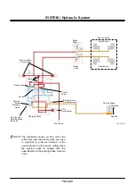
In this way, the force to raise the front attachment
is relieved to the hydraulic oil tank, and the force
to lower the front attachment is absorbed by the
ride control accumulator. Therefore, the machine
travels stably when traveling on rough roads.
Содержание ZW180
Страница 1: ......
Страница 2: ......
Страница 8: ...4GDT 1 2 Blank ...
Страница 10: ...GENERAL Specification T1 1 2 Blank ...
Страница 38: ...GENERAL Component Specifications T1 3 14 Blank ...
Страница 39: ...MEMO ...
Страница 40: ...MEMO ...
Страница 42: ...4GDT 2 2 Blank ...
Страница 56: ...SYSTEM Control System T2 1 14 Blank ...
Страница 82: ...SYSTEM Control System T2 1 40 Blank ...
Страница 92: ...SYSTEM Control System T2 1 50 Blank ...
Страница 106: ...SYSTEM Control System T2 1 64 Blank ...
Страница 116: ...SYSTEM ECM System T2 2 10 Blank ...
Страница 128: ...SYSTEM Hydraulic System T2 3 12 Blank ...
Страница 147: ...SYSTEM Hydraulic System T2 3 31 Blank ...
Страница 150: ...SYSTEM Hydraulic System T2 3 34 Blank ...
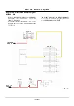
Страница 165: ...SYSTEM Electrical System T2 4 15 T4GD 02 04 019 Battery Relay Battery SC FC L L B E D Alternator B Regulator F R ...
Страница 184: ...SYSTEM Electric System T2 4 34 Blank ...
Страница 185: ...MEMO ...
Страница 186: ...MEMO ...
Страница 195: ...COMPONENT OPERATION Pump Device T3 1 7 Blank ...
Страница 210: ...COMPONENT OPERATION Control Valve T3 2 2 Component Layout T4GB 03 02 003 1 2 3 4 5 7 8 9 10 11 7 6 ...
Страница 212: ...COMPONENT OPERATION Control Valve T3 2 4 T4GB 03 02 003 1 2 3 4 5 7 8 9 10 11 7 6 ...
Страница 214: ...COMPONENT OPERATION Control Valve T3 2 6 T4GB 03 02 003 1 2 3 4 5 7 8 9 10 11 7 6 ...
Страница 226: ...COMPONENT OPERATION Control Valve T3 2 18 Blank ...
Страница 232: ...COMPONENT OPERATION Control Valve T3 2 24 Blank ...
Страница 239: ...COMPONENT OPERATION Hydraulic Fan Motor T3 3 7 T4GB 03 03 005 7 8 From Fan Pump P B A 12 T To Hydraulic Oil Tank ...
Страница 248: ...COMPONENT OPERATION Steering Pilot Valve T3 4 6 Blank ...
Страница 258: ...COMPONENT OPERATION Steering Valve T3 5 10 Blank ...
Страница 274: ...COMPONENT OPERATION Pilot Valve T3 6 16 Blank ...
Страница 282: ...COMPONENT OPERATION Pilot Valve T3 6 24 Blank ...
Страница 299: ...COMPONENT OPERATION Ride Control Valve T3 8 5 Blank ...
Страница 306: ...COMPONENT OPERATION Ride Control Valve T3 8 12 Blank ...
Страница 316: ...COMPONENT OPERATION Drive Unit T3 9 10 Forward Clutch Shaft T4GD 03 09 005 Reverse Clutch Shaft T4GD 03 09 006 ...
Страница 345: ...COMPONENT OPERATION Drive Unit T3 9 39 T107 02 07 005 1 Spool 2 Spring 3 Solenoid T P S a a 1 2 3 ...
Страница 348: ...COMPONENT OPERATION Drive Unit T3 9 42 Blank ...
Страница 371: ...MEMO ...
Страница 372: ...MEMO ...
Страница 374: ......


