SYSTEM / Control System
T2-1-36
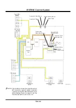
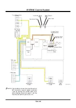
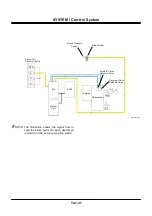
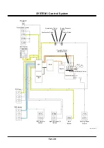
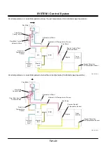
Clutch Cut Control
Purpose: To release the FNR clutch of the transmis-
sion in order to make the most of the engine
torque by operating the brake during opera-
tion of the front attachment.
Depressing amount of stepping the brake at
the time of declutching can be selected from
among three kinds depending on the op-
erator’s preference.
Operation:
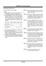
1. When either mode of the clutch cut position switch
is selected, voltage according to the selected
mode is transmitted to MC.
Mode OFF S N D
Input
Voltage
1 V
2 V
3 V
4 V
2. MC starts the corresponding clutch cut control
program.
•
Clutch cut is not made in OFF mode.
•
In mode S, clutch cut is made at output voltage of
the brake pressure sensor beyond the set pressure
of mode S, and clutching is made again at output
voltage below that of mode S.
•
In mode N, clutch cut is made at output voltage of
the brake pressure sensor beyond the set pressure
of mode N, and clutching is made again at output
voltage below that of mode N.
•
In mode D, clutch cut is made at output voltage of
the brake pressure sensor beyond the set pressure
of mode D, and clutching is made again at output
voltage below that of mode D.
3. In case the brake pedal is depressed in mode S,
the signal from the brake pressure sensor is
transmitted to MC.
4. When the signal is higher than the set voltage, MC
declutches by lowering the signal transmitted to
the excited solenoid valve among the respective
solenoid valves.
5. In case the brake pressure is lowered below the
set pressure by reducing the depressing amount
of the brake pedal, the signal transmitted to the
clutch solenoid valve is raised again, and clutch-
ing is made.
NOTE: In case either of the clutch cut position
switch and brake pressure sensor becomes
out of order, clutch cut control is not made.
NOTE: Each mode switch of the clutch cut position
switch is supplied with respectively different
voltages from the monitor unit, and when
the switch selects a mode, MC judges
which mode has been selected by the input
voltage.
Содержание ZW180
Страница 1: ......
Страница 2: ......
Страница 8: ...4GDT 1 2 Blank ...
Страница 10: ...GENERAL Specification T1 1 2 Blank ...
Страница 38: ...GENERAL Component Specifications T1 3 14 Blank ...
Страница 39: ...MEMO ...
Страница 40: ...MEMO ...
Страница 42: ...4GDT 2 2 Blank ...
Страница 56: ...SYSTEM Control System T2 1 14 Blank ...
Страница 82: ...SYSTEM Control System T2 1 40 Blank ...
Страница 92: ...SYSTEM Control System T2 1 50 Blank ...
Страница 106: ...SYSTEM Control System T2 1 64 Blank ...
Страница 116: ...SYSTEM ECM System T2 2 10 Blank ...
Страница 128: ...SYSTEM Hydraulic System T2 3 12 Blank ...
Страница 147: ...SYSTEM Hydraulic System T2 3 31 Blank ...
Страница 150: ...SYSTEM Hydraulic System T2 3 34 Blank ...
Страница 165: ...SYSTEM Electrical System T2 4 15 T4GD 02 04 019 Battery Relay Battery SC FC L L B E D Alternator B Regulator F R ...
Страница 184: ...SYSTEM Electric System T2 4 34 Blank ...
Страница 185: ...MEMO ...
Страница 186: ...MEMO ...
Страница 195: ...COMPONENT OPERATION Pump Device T3 1 7 Blank ...
Страница 210: ...COMPONENT OPERATION Control Valve T3 2 2 Component Layout T4GB 03 02 003 1 2 3 4 5 7 8 9 10 11 7 6 ...
Страница 212: ...COMPONENT OPERATION Control Valve T3 2 4 T4GB 03 02 003 1 2 3 4 5 7 8 9 10 11 7 6 ...
Страница 214: ...COMPONENT OPERATION Control Valve T3 2 6 T4GB 03 02 003 1 2 3 4 5 7 8 9 10 11 7 6 ...
Страница 226: ...COMPONENT OPERATION Control Valve T3 2 18 Blank ...
Страница 232: ...COMPONENT OPERATION Control Valve T3 2 24 Blank ...
Страница 239: ...COMPONENT OPERATION Hydraulic Fan Motor T3 3 7 T4GB 03 03 005 7 8 From Fan Pump P B A 12 T To Hydraulic Oil Tank ...
Страница 248: ...COMPONENT OPERATION Steering Pilot Valve T3 4 6 Blank ...
Страница 258: ...COMPONENT OPERATION Steering Valve T3 5 10 Blank ...
Страница 274: ...COMPONENT OPERATION Pilot Valve T3 6 16 Blank ...
Страница 282: ...COMPONENT OPERATION Pilot Valve T3 6 24 Blank ...
Страница 299: ...COMPONENT OPERATION Ride Control Valve T3 8 5 Blank ...
Страница 306: ...COMPONENT OPERATION Ride Control Valve T3 8 12 Blank ...
Страница 316: ...COMPONENT OPERATION Drive Unit T3 9 10 Forward Clutch Shaft T4GD 03 09 005 Reverse Clutch Shaft T4GD 03 09 006 ...
Страница 345: ...COMPONENT OPERATION Drive Unit T3 9 39 T107 02 07 005 1 Spool 2 Spring 3 Solenoid T P S a a 1 2 3 ...
Страница 348: ...COMPONENT OPERATION Drive Unit T3 9 42 Blank ...
Страница 371: ...MEMO ...
Страница 372: ...MEMO ...
Страница 374: ......


