SYSTEM / Hydraulic System
T2-3-28
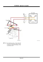
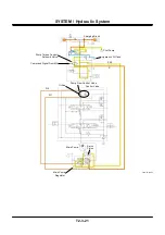
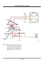
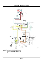
Steering Shockless Circuit
•
Pilot pressure oil supplied from the steering pilot
valve to the spool end of the steering valve is
reduced by passing through the orifice inside the
steering valve, and is applied to the spool end of
the opposite side. In this way, the vehicle shock
due to sudden shift of the spool is reduced, and
stable steering operation is possible. (Refer to the
COMPONENT OPERATION / Steering Valve
group.)
•
The steering accumulators are provided in order
to reduce the joggling of the vehicle when
stopping the steering wheel rotation.
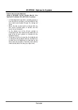
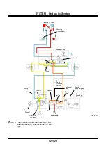
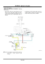
Emergency Steering Circuit (Optional)
•
When traveling, if the main pump delivery is
stopped or drastically decreased caused by
failure of the engine or the main pump, the
pressure sensing signal of the pump delivery
pressure switch is transmitted into the monitor
controller. Then, the monitor controller starts the
motor of the emergency steering pump unit.
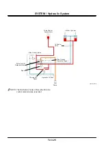
•
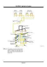
Pressure oil is supplied from the emergency
steering pump for 1 minute. Therefore, steering
operation is possible.
•
When 1 minute have passed or when the key
switch has been turned OFF after moving the
vehicle to a safe place, the emergency steering
pump stops.
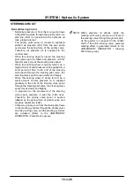
NOTE: When the engine is started, the monitor
unit automatically starts the emergency
steering pump unit in order to confirm its
function. When the pressure sensing signal
of the emergency steering pump delivery
pressure switch is transmitted to the
monitor unit, the emergency steering pump
unit automatically stops.
Содержание ZW180
Страница 1: ......
Страница 2: ......
Страница 8: ...4GDT 1 2 Blank ...
Страница 10: ...GENERAL Specification T1 1 2 Blank ...
Страница 38: ...GENERAL Component Specifications T1 3 14 Blank ...
Страница 39: ...MEMO ...
Страница 40: ...MEMO ...
Страница 42: ...4GDT 2 2 Blank ...
Страница 56: ...SYSTEM Control System T2 1 14 Blank ...
Страница 82: ...SYSTEM Control System T2 1 40 Blank ...
Страница 92: ...SYSTEM Control System T2 1 50 Blank ...
Страница 106: ...SYSTEM Control System T2 1 64 Blank ...
Страница 116: ...SYSTEM ECM System T2 2 10 Blank ...
Страница 128: ...SYSTEM Hydraulic System T2 3 12 Blank ...
Страница 147: ...SYSTEM Hydraulic System T2 3 31 Blank ...
Страница 150: ...SYSTEM Hydraulic System T2 3 34 Blank ...
Страница 165: ...SYSTEM Electrical System T2 4 15 T4GD 02 04 019 Battery Relay Battery SC FC L L B E D Alternator B Regulator F R ...
Страница 184: ...SYSTEM Electric System T2 4 34 Blank ...
Страница 185: ...MEMO ...
Страница 186: ...MEMO ...
Страница 195: ...COMPONENT OPERATION Pump Device T3 1 7 Blank ...
Страница 210: ...COMPONENT OPERATION Control Valve T3 2 2 Component Layout T4GB 03 02 003 1 2 3 4 5 7 8 9 10 11 7 6 ...
Страница 212: ...COMPONENT OPERATION Control Valve T3 2 4 T4GB 03 02 003 1 2 3 4 5 7 8 9 10 11 7 6 ...
Страница 214: ...COMPONENT OPERATION Control Valve T3 2 6 T4GB 03 02 003 1 2 3 4 5 7 8 9 10 11 7 6 ...
Страница 226: ...COMPONENT OPERATION Control Valve T3 2 18 Blank ...
Страница 232: ...COMPONENT OPERATION Control Valve T3 2 24 Blank ...
Страница 239: ...COMPONENT OPERATION Hydraulic Fan Motor T3 3 7 T4GB 03 03 005 7 8 From Fan Pump P B A 12 T To Hydraulic Oil Tank ...
Страница 248: ...COMPONENT OPERATION Steering Pilot Valve T3 4 6 Blank ...
Страница 258: ...COMPONENT OPERATION Steering Valve T3 5 10 Blank ...
Страница 274: ...COMPONENT OPERATION Pilot Valve T3 6 16 Blank ...
Страница 282: ...COMPONENT OPERATION Pilot Valve T3 6 24 Blank ...
Страница 299: ...COMPONENT OPERATION Ride Control Valve T3 8 5 Blank ...
Страница 306: ...COMPONENT OPERATION Ride Control Valve T3 8 12 Blank ...
Страница 316: ...COMPONENT OPERATION Drive Unit T3 9 10 Forward Clutch Shaft T4GD 03 09 005 Reverse Clutch Shaft T4GD 03 09 006 ...
Страница 345: ...COMPONENT OPERATION Drive Unit T3 9 39 T107 02 07 005 1 Spool 2 Spring 3 Solenoid T P S a a 1 2 3 ...
Страница 348: ...COMPONENT OPERATION Drive Unit T3 9 42 Blank ...
Страница 371: ...MEMO ...
Страница 372: ...MEMO ...
Страница 374: ......

