SJ700
2
Inverter
Oper
ati
ons
and Monitor
ing
4–35
Force Terminal
Mode
The purpose of this intelligent input is to allow a device to force the inverter to allow control of
the following two parameters via the control terminals:
• A001 - Frequency source setting (01 = control terminals [FW] and [RV])
• A002 - Run command source setting (01 = control terminals [O] or [OI])
Some applications will require one or both settings above to use a source other than the
terminals. You may prefer to normally use the inverter’s keypad and potentiometer, or to use the
ModBus network for control, for example. However, an external device can turn ON the
[F-TM] input to force the inverter to (temporarily) allow control (frequency source and Run
command) via control terminals. When the [F-TM] input is OFF, then the inverter uses the
regular sources specified by A001 and A002 again.
When changing the [F-TM] state during Run Mode (inverter is driving the motor), the inverter
will stop the motor before the new [F-TM] state takes effect.
Torque Control
Enable
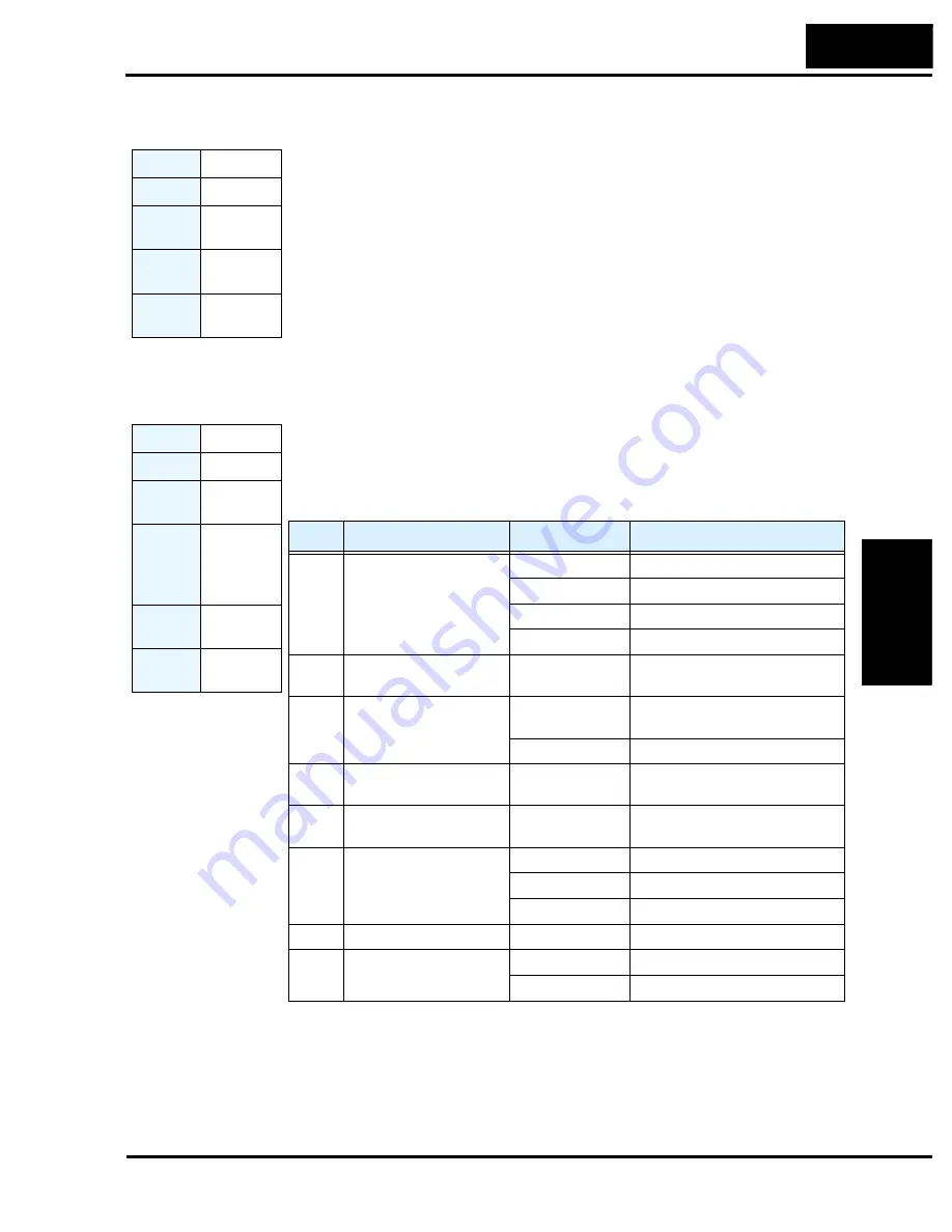
The torque control enable function is available in the
vector control with encoder feedback
mode (A044 = 05). You can use the inverter not only in speed control or pulse train position
control but also with the torque control function. Suitable applications include material winding
machines.
The torque command input is enabled when the [ATR] intelligent input (assigned with option
code 52) is ON. You can select one of four torque command input methods (digital operator
and three analog input terminals) by the torque command input selection.
Opt. Code
51
Symbol
[F–TM]
Valid for
Inputs
[1] to [8]
Required
Settings
A001, A002
Default
terminal
Requires
config.
Opt. Code
52
Symbol
[ATR]
Valid for
Inputs
[1] to [8]
Required
Settings
A044 = 05,
P033, P034,
P035, P039,
P040, P036,
P037, P038
Monitor
Settings
D009, D010,
D012
Default
terminal
Requires
config.
Code
Function
Data or Range
Description
P033
Torque command input
selection
00
[O] terminal
01
[OI] terminal
02
[O2] terminal
03
Inverter keypad (P034)
P034
Torque command setting
0. to 200. (%)
Torque setting for the input from
the digital operator (P033 = 03)
P035
Torque command polarity
select
00
Indicated by signal polarity at
[O2] terminal
01
Depends on motor direction
P039
Forward speed limit for
torque-control mode
0.00 to maximum
frequency (Hz)
—
P040
Reverse speed limit for
torque-control mode
0.00 to maximum
frequency (Hz)
—
P036
Torque bias mode
00
Disable
01
Inverter keypad (P037)
02
[O2] terminal input
P037
Torque bias value
-200. to 200. (%)
P038
Torque bias polarity
00
Indicated by polarity
01
Depends on motor direction
Содержание SJ700-004LFU2
Страница 2: ......
Страница 42: ......
Страница 162: ......
Страница 241: ...Inverter System Accessories In This Chapter page Introduction 2 Component Descriptions 3 Dynamic Braking 6 5 ...
Страница 248: ......
Страница 278: ......
Страница 279: ...Glossary and Bibliography In This Appendix page Glossary 2 Bibliography 6 A ...
Страница 359: ...Drive Parameter Settings Tables In This Appendix page Introduction 2 Parameter Settings for Keypad Entry 2 C ...
Страница 378: ......
Страница 390: ......


